DONGHE Şirketi ile iletişime geçin


Ağustos 2026'da güncellendi
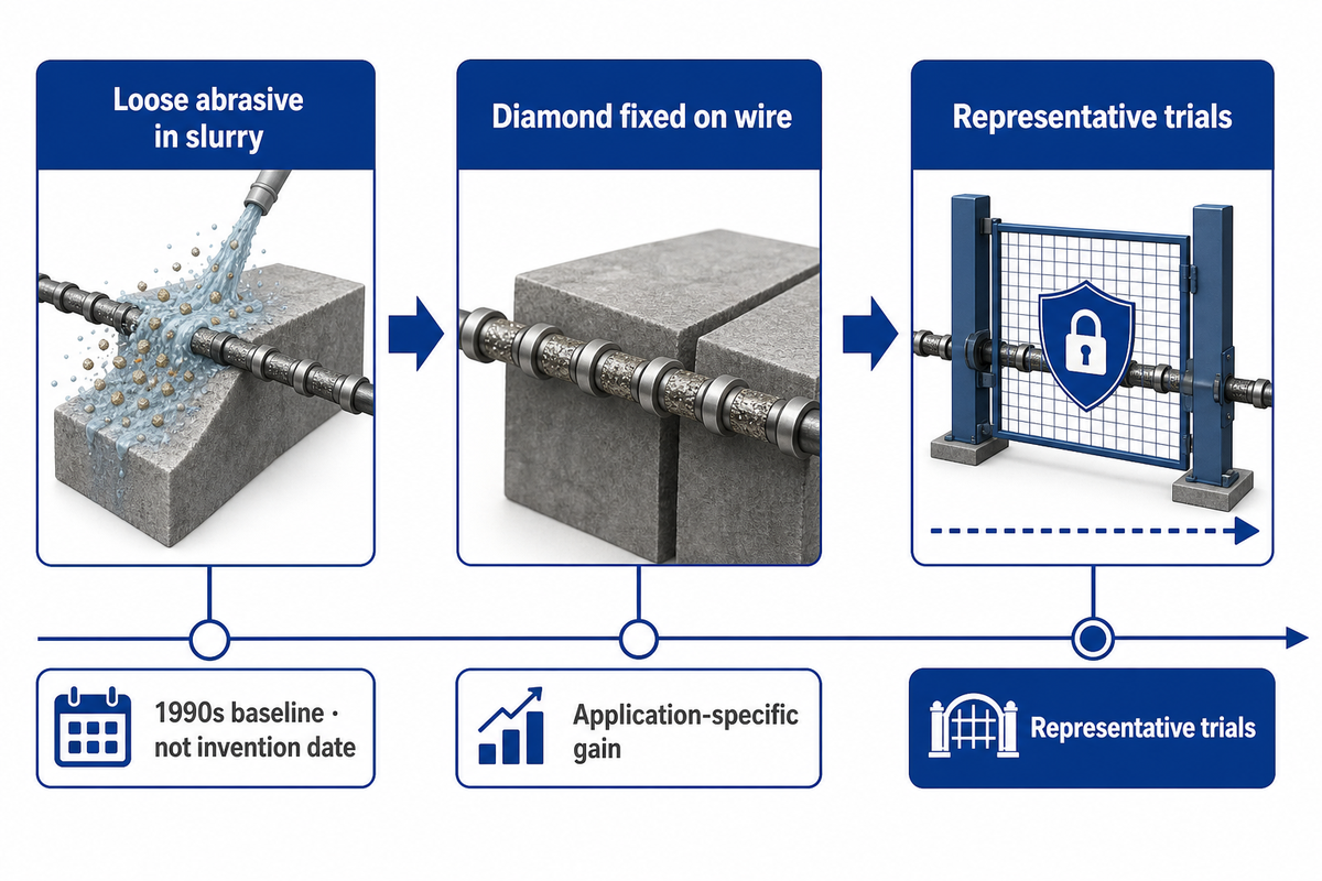
Elmas tel kesme teknolojisi, hareketli telin bağlı elmas taşıdığı sabit aşındırıcı bir işlemdir; bu makale bunu daha önceki gevşek aşındırıcı tel testereyle karşılaştırıyor ve teknoloji 1990'da başlamadı. Sonuç olarak: 1990–2026 penceresi boyunca, spesifik endüstriyel değişim, bulamaç yol vererek, uygulama uygulama, hareketli tel üzerine sabitlenmiş elmas tarafından taşınan gevşek aşındırıcıydı.Kazancı “ne pahasına olursa olsun hız” değil, aşınma, titreşim, yay, kırılma ve aşağı akış kalitesinde yeni risklerle daha doğrudan, kontrol edilebilir bir kesme sistemiydi.
TL;DR
- Gevşek aşındırıcı tel testereyle, bulamaçtaki serbest kumun taşınması için çıplak bir tel kullanılır; sabit aşındırıcı tel, telin üzerinde elmas taşır.
- Bu makalede, 1990'lar, elmas kaplı telin buluş tarihi değil, bulamaç çok telli gofretleme için temeldir.
- Sabit elmas tel, tanımlanmış uygulamalarda kerf ve işlem süresini azaltabilir, ancak hiçbir evrensel üretkenlik çarpanı malzeme, makine, tel ve kalite hedefindeki farklılıklardan sağ çıkamaz.
- Bazı oksit-seramik araştırmalar hala bulamaç tel testereyi kullanıyor, bu nedenle migrasyonun varsayılmak yerine kanıtlanması gerekiyor.
- Beş kapılı bir ön ekran bir RFQ'yu yapılandırabilir, ancak alıcının çizimi, geçerli geçerli standartlar ve temsili denemeler yetkili olmaya devam eder.
1990 ve 2026 Yılları Arasında Elmas Tel Kesme Teknolojisinde Neler Değişti?
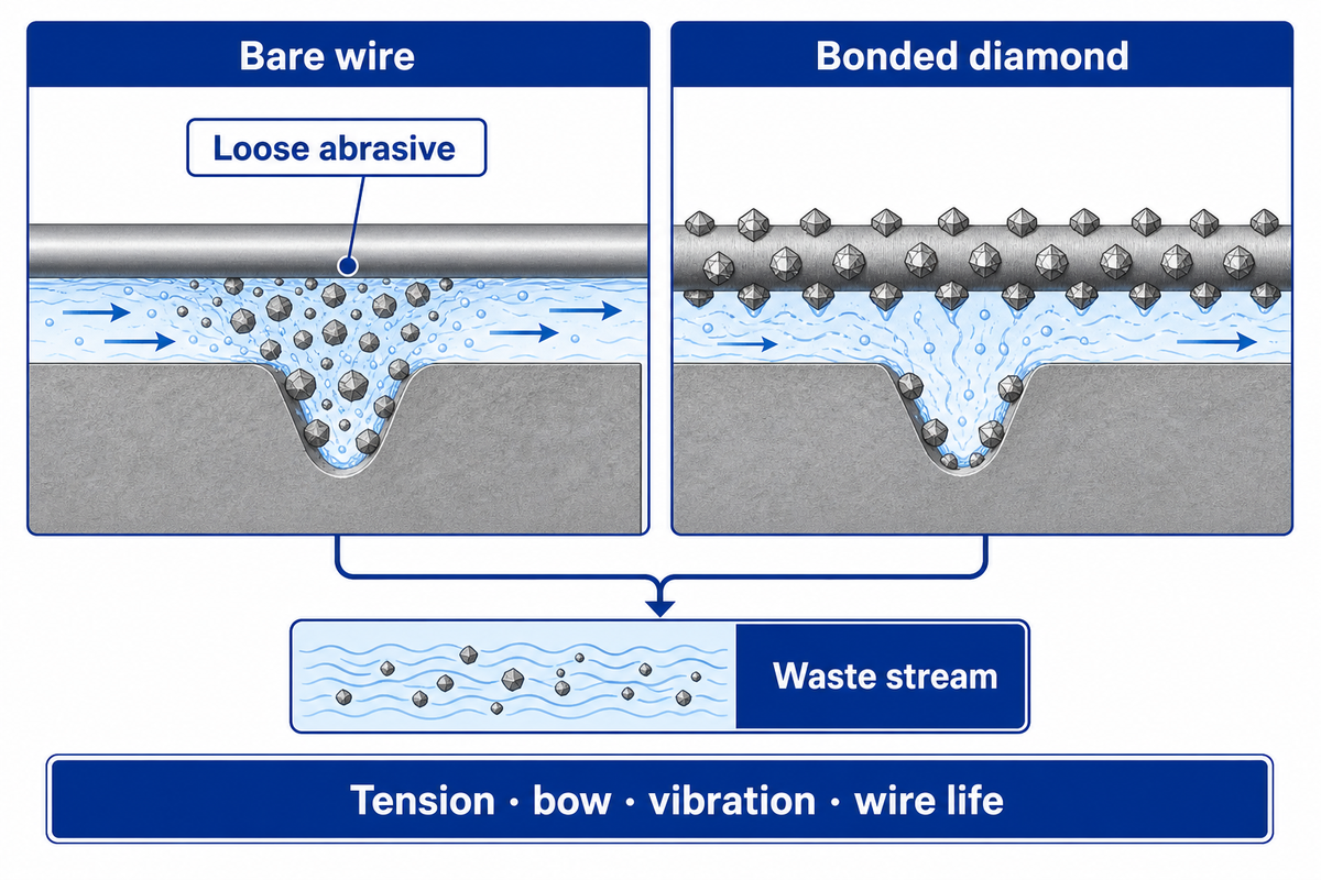
Aşındırıcı konum merkezi değişiklikti.bulamaç tel testerede,hareketli bir çıplak tel kesime gevşek aşındırıcı taşır.Sabit aşındırıcı testerede elmas taneleri tele yapıştırılır.Bu değişiklik çıkarma yolunu basitleştirdi,ama aynı zamanda yönetimi kaplama durumuna,gerilmeye,yay,titreşime,soğutma sıvısı akışına ve tel ömrüne aktardı.
Önemli bir tarihi sınır vardır A 1964 elmas kaplı tel patenti örgülü tel üzerinde nikel-elektrolize elmas kumunu tarif eder ve kaplamalı tek telli testerelerin zaten var olduğunu söyler.Bu nedenle, 1990 bir menşe iddiası değildir.Özellikle hassas gofretlemede burada incelenen bulamaçtan sabit geçiş penceresinin başlangıcını işaret eder.
| Karar boyutu | Çıplak tel üzerinde gevşek aşındırıcı | Tele bağlı elmas |
|---|---|---|
| Aşındırıcı konum | Bulamaç içinde asılı serbest parçacıklar | Bir bağ veya metal tabaka ile sabitlenmiş elmas taneleri |
| Kaldırma yolu | Kablolu taşıma kum; parçacıklar tel ile iş parçası arasında yuvarlanır, kayar ve girinti oluşturur | Açıkta kalan elmas iş parçasını tel yüzeyinden birleştirir |
| Birincil kontroller | Bulamaç konsantrasyonu, kum durumu, sıvı dağılımı, tel hızı, besleme ve ağ davranışı | Elmas boyutu ve tutma, tel hızı, besleme, gerilim, yay, titreşim, soğutma sıvısı ve kaplama aşınması |
| Atık akışı | Harcanmış taşıyıcı sıvı, gevşek aşındırıcı ve ince taneli kerf | Kesme sıvısı, ince taneler, aşınmış tel ve bağ veya kaplama kalıntıları |
| Tipik kısıtlama | Bulamaç hazırlama, sirkülasyon, ayırma ve uzaklaştırma tutarlılığı | Tel inceldikçe veya kesme durumu değiştikçe daha dar parametre penceresi |
Kapsam: Bu defter aşındırıcı yerleştirme ve kontrol mantığını karşılaştırır.her bulamaç sisteminin, kaplanmış telin, boncuk telinin veya makine mimarisinin aynı şekilde davrandığı anlamına gelmez. Kaynaklar: Clark ve ark. (2003), Li ve ark. (2023) ve gözden geçirilmiş 1964 patent kaydı.
Anahtar paket servisi: Aşındırıcı sıvıdan tele doğru hareket etti, ancak mühendislik yükü daha sıkı bir makine – tel – malzeme sistemine geçti.
Neden Çok Telli Bulamaç Testere 1990'ların Temel Çizgisi Oldu
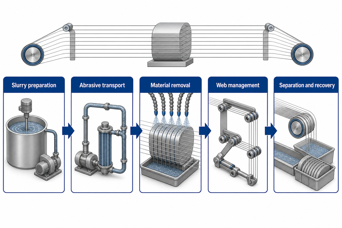
Bulamaç çok telli testere bir ölçek problemini çözdü.İnce tellerden oluşan bir ağ, bir külçeden birçok levhayı tek seferde dilimleyebilirken, gevşek aşındırıcı gerçek kesme eylemini sağladı.Yarı iletken ve fotovoltaik levha formatlarını büyütmek için bu kombinasyon, eski bıçak bazlı yaklaşımlardan daha küçük kerf sundu ve paralel dilimlemeyi pratik hale getirdi.
Clark ve meslektaşlarının 2003 süreç izleme makalesi 1990'larda erken tel testere levha dilimleme gelişimini çıplak tel üzerinde gevşek aşındırıcı bulamaç olarak tanımlar.Bu mekanizmaya genellikle üç gövdeli aşınma denir: iş parçası ve tel ana gövdelerdir, serbest parçacıklar aralarında hareket eder. Tel, bulamacı temas bölgesi boyunca taşırken silikon karbür veya elmas tanecik girintili, yuvarlanabilir ve kayabilir.
- Bulamaç hazırlama: aşındırıcı konsantrasyonu, taşıyıcı özellikleri, sıcaklık ve kirlenme durumu belirlenir.
- Taşıma: hareketli tel aşındırıcıyı sürükler ve onu kerfin içine taşır.
- Malzeme kaldırma: parçacıklar sert, kırılgan bir yüzeyi tekrar tekrar girintiler ve kırarlar.
- Web yönetimi: besleme, hız, tel yolu ve bulamaç dağıtımı birçok eşzamanlı kesimde sabit kalmalıdır.
- Ayırma ve kurtarma: akışkan, aşındırıcı ve kerf katıları, yönetilmesi gereken karışık bir atık akışı bırakır.
Bu prosesi “ilkel” olarak adlandırmak endüstriyel değerini kaçırır. Telin taşıma fonksiyonunu aşındırıcının kesme fonksiyonundan ayırdı ve aynı anda birçok ince kesime izin verdi. Üreticiler daha kısa döngüler, daha ince levhalar, daha az kerf, daha basit sıvı kullanımı ve daha tekrarlanabilir kontrol peşinde koştukça sınırlamaları daha görünür hale geldi. Bu basınçlar sabit aşındırıcı sistemler için alan yarattı; bulamaç çoklu tel testerenin mümkün kıldığı şeyi silmezler.
Anahtar paket servisi: Bulamaç testereleme, yalnızca değiştirilmeyi bekleyen kalitesiz bir teknoloji değil, ölçeğe olanak sağlayan bir üretim temel çizgisiydi.
Sabit Aşındırıcı Çekim: Elmas Nasıl Telin Bir Parçası Oldu
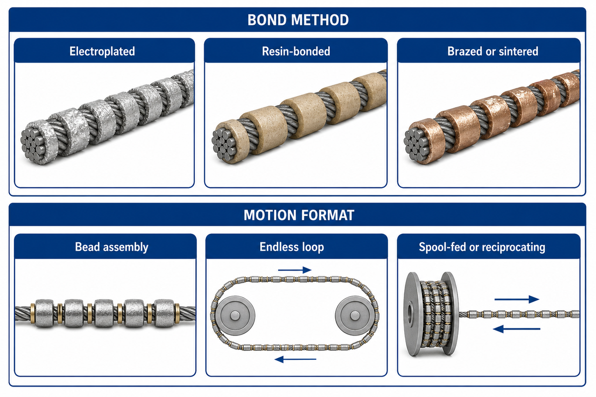
Sabit aşındırıcı tel aletin kendisini değiştirir Elmas, elektrokaplama, reçine, sert lehimleme, sinterleme veya bir boncuk düzeneği ile bir çelik veya başka bir tel alt tabaka üzerinde tutulur.Yine de “elmas tel” tek bir değiştirilebilir ürün sınıfı değildir: bağ yöntemi, tel geometrisi, hareket, aşındırıcı maruz kalma ve uygulama ölçeğinin tümü kesme davranışını değiştirir.
Elektrolize ince tel, metal bir katmanda tutulan elması açığa çıkarır ve hassas kesimde yaygındır.Reçine bağlı tel, tane desteği ve yenilenmenin farklı bir dengesini sunabilir.Taş veya sinterlenmiş yapılar diğer yük ve aşınma koşullarını ele alır.Taş veya betonda kullanılan boncuklu kablo, elmas segmentlerini çok daha büyük bir taşıyıcı boyunca yerleştirir.Sonsuz döngüler sürekli olarak dolaşır; makara beslemeli veya pistonlu sistemler sonlu bir tel uzunluğunu tersine çevirir veya yönetir.Her bir elmas tel türü, elektrokaplamalı veya bağlı formlarda endüstriyel elmas parçacıkları kullanabilirken, daha büyük elmas boncuklar, taş veya beton ölçekli işler için elmas segmentlerle gömülü bir tel oluşturur. Bir elmas tel döngüsü, sonsuz elmas tel kesmeyi destekler, oysa makara beslemeli tasarımlar, kontrollü tel dağıtımına ihtiyaç duyan kesme uygulamalarına uygundur.
| Biçimlendir | Neyi tarif ettiğini | Faydalı uygulama sorusu | Doğrulanacak sınır |
|---|---|---|---|
| Elektrolize ince tel | Elektro-çökeltilmiş bir metal katman tarafından tutulan elmas | Gerekli kerf ve yüzey durumu mevcut çap ve kumla uyumlu mu? | Tahıl maruziyeti, kaplama tekdüzeliği, aşınma ve tel mukavemeti |
| Reçine bağlı tel | Elmas polimerik bir bağ içinde tutuldu | Bağ davranışı iş parçasına ve istenen yüzeye uygun mu? | Isı, yükleme, tane yenileme ve bağ ömrü |
| Sonsuz döngü | Kılavuz tekerleklerin etrafında sürekli hareket eden kapalı bir döngü | Sürekli tek yönlü hareket gerekli kesimi veya kurulumu iyileştirir mi? | Eklem kalitesi, döngü takibi, gerilim aralığı ve değiştirme yöntemi |
| Makara veya pistonlu tel | Depolama ve kılavuz sistemleri arasında seyahat eden veya tersine dönen, yönetilen bir uzunluk | Kesim boyunca taze ve kullanılmış tel nasıl dağıtılacak? | Tersine çevirme işaretleri, kullanım dağılımı, seyahat kontrolü ve kablo tüketimi |
| Çok telli web | Birçok paralel tel açıklığı birden fazla parçayı veya levhayı dilimlemektedir | Paralel çıktı, tek kesim esnekliğinden daha mı önemli? | Adım, ağ sapması, düzgün sıvı dağıtımı ve parçadan parçaya değişim |
| Boncuklu kablo | Daha büyük bir kablo boyunca aralıklı elmas segmentler | Bu büyük kesitli bir taş mı, taş ocağı mı, yoksa inşaat kesimi mi? | Boncuk tasarımı, kablo hızı, güçlendirme, erişim ve güvenlik planı |
Kapsam: Bu sınıflandırma bir kategori hatasını önler; evrensel bir öneri değildir.Son seçim, tedarikçinin kablo spesifikasyonunu ve makinenin doğrulanmış çalışma aralığını gerektirir.
O ayrım kötü tarihsel iddiaları da önler.bir bile kaplamalı tek telli patent, bir fotovoltaik çok telli ağ, sonsuz bir hassas döngü ve bir taş ocağı kablosunun tümü elmas içerebilir, ancak bir benimseme eğrisini paylaşmazlar. Araştırma görünümü, üretimin benimsenmesi ve pazar hakimiyeti her uygulama için ayrı ayrı tarihlendirilmelidir.
Anahtar paket servisi: Bağ, tel formatı, hareket, makine mimarisi ve uygulamayı belirtin - sadece “elmas tel” değil”
Endüstri Neden Gevşek Aşındırıcıdan Elmas Bağlı Tele Geçti
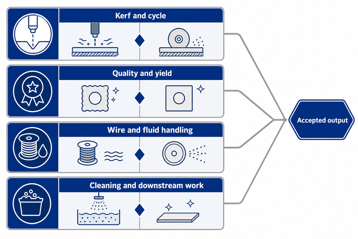
Sabit aşındırıcı, kesme noktalarını doğrudan hareketli telin üzerine yerleştirebildiği, dolaşımdaki gevşek kum karışımına olan bağımlılığı azaltabildiği ve uygun sistemlerde daha küçük kerf veya daha kısa döngüleri destekleyebildiği için çekici hale geldi. Bunlar evrensel sonuçlar değil mühendislik fırsatlarıdır. Sağlam bir karşılaştırma kalite, verim, tel kullanımı, sıvı taşıma, bakım ve aşağı yönde işlemeyi içerir.
| Sürücü | Neden sabit aşındırıcı yardımcı olabilir | Kazancı iptal edebilecek şey | Neyi ölçmek |
|---|---|---|---|
| Verim | Doğrudan sunulan elmas taneleri, eşleşen bir işlemde malzeme çıkarma kapasitesini artırabilir | Aşırı besleme, dengesiz yay, ısı, cam, titreşim veya erken tel aşınması | Planlanan çalışmanın tamamında saatte iyi parçalar, yalnızca yoğun besleme değil |
| Kerf ve malzeme verimi | İnce tel, kesim tarafından tüketilen malzemenin genişliğini azaltabilir | Tel dolaşımı, titreşim, kenar hasarı, kırılma veya aşağı yönde reddedilme | Kerf dağıtımı, satılabilir verim, kırılma ve yeniden işleme |
| Sıvı taşıma | Su bazlı veya daha basit bir kesme sıvısı, gevşek aşındırıcı bir bulamaç devresinin yerini alabilir | Yeni filtreleme, korozyon, ince taneler, kullanılmış tel veya geri kazanım gereksinimleri | Kabul edilen parça başına toplam sıvı, filtreleme, temizleme, atık ve geri kazanım maliyeti |
| Yüzey bütünlüğü | Kontrollü sabit bir alet, işlemi daha tekrarlanabilir hale getirebilir | Periyodik işaretler, yüzey altı hasarı, kum boyutu etkileri ve kablo durumu değişiklikleri | Pürüzlülük, hasar derinliği, dalgalılık, düzlük, çözgü ve duruma göre aşağı akış tepkisi |
| Proses kontrolü | Makine sinyalleri tanımlanmış bir tel alete daha doğrudan bağlanabilir | Kontrol ayarları malzemeler, geometriler veya tel partileri arasında aktarılmayabilir | Zaman içinde kuvvet veya yük eğilimi, gerilim, yay, titreşim, alarmlar, durmalar ve yetenek |
Kaynaklar ve kapsam: Clark ve ark. (2003), Li ve ark. (2023), Yang ve ark. (2022) ve Rockies Ulusal Laboratuvarı araştırma kaydı. Bireysel çalışmalarda bildirilen değerler duruma özel kalır. Doğrudan yöntem seçimi sayfası için mevcut olana bakın elmas tel testere vs bulamaç testere karşılaştırma.
Bir sürdürülebilirlik iddiası aynı disipline ihtiyaç duyar Gevşek aşındırıcının çıkarılması sıvı hacmini ve kullanımını değiştirebilir, ancak sistem sınırı yine de enerji, su, filtreleme, kullanılmış tel, ince taneler, temizlik, reddedilen parçalar ve geri kazanım kalitesini içermelidir. “Bulamaç yok” bir süreç açıklamasıdır; tek başına doğrulanmış bir çevresel sonuç değildir.
Anahtar paket servisi: Kabul edilen çıktıyı ve izole edilmiş bir besleme hızını veya bulamaç yokluğunu değil, tüm atık ve sarf malzemeleri sistemini karşılaştırın.
Elmas Tel Kesme Teknolojisi Zaman Çizelgesi: 1990–2026
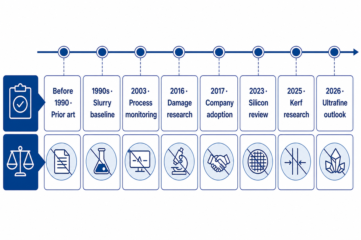
Bu geçiş en iyi şekilde bir dizi kanıt türü olarak okunur. Patentler bir kavramın var olduğunu gösteriyor. Araştırma makaleleri neyin ölçüldüğünü gösteriyor Bir fabrika yatırımı tek bir benimseme olayını kaydediyor İncelemeler daha geniş bir teknik yönü tanımlıyor Bunların hiçbiri tek başına küresel pazar hakimiyetini kanıtlamıyor ve farklı sektörler farklı hızlarda hareket ediyor.
| Dönem | Kanıt türü | Kanıtların desteklediği | Çözülmemiş kalan |
|---|---|---|---|
| 1990'dan önce | Önceki sanat | 1964 tarihli bir patent, örgülü tel üzerindeki nikel-elektrolize elmas kumunu açıklamaktadır ve daha önceki kaplamalı tek telli testereleri kabul etmektedir | Ticari ölçek, başvuru payı ve performans patent tarafından belirlenmemiştir |
| 1990'lar | Tarihsel araştırma bağlamı | Çıplak tel üzerinde gevşek aşındırıcı bulamaç, levha dilimleme taban çizgisi olarak geliştirildi | Sektörler arasında tek bir küresel buluş veya benimsenme tarihi geçerli değildir |
| 2003 | Süreç izleme kağıdı | Sabit aşındırıcı kesme, kuvvet, hız, aşağı besleme, yay açısı ve gerilim yoluyla incelenir | Kağıdın makine ve malzeme koşulları evrensel ayarlar değildir |
| 2016 | En son teknoloji inceleme ve silikon hasarı araştırması | Tel testere mekanizmaları sentezlenir; hasar proses hareketi, kum boyutu ve tel kullanımıyla bağlantılıdır | Aşağı yöndeki gereksinimler ve kablo yaşam döngüsü hâlâ kabulü yönetmektedir |
| 2017 | Şirket evlat edinme olayı | PV Magazine, Meyer Burger'in SolarWorld'ün Freiberg tesisi için sipariş edilen elmas tel ekipmanına US$7,9 milyon değerinde değer verdiğini ve teslimat ve devreye almanın 2017'nin 2. çeyreği için planlandığını bildirdi; SolarWorld'ün daha geniş yatırımı entegrasyon maliyetlerini de içeriyordu | Bir ekipman siparişi sektör çapında bir benimseme yüzdesi değildir |
| 2023 | Hakemli inceleme | Sabit elmas tel, baskın monokristalin-silikon levha kesme yöntemi olarak tanımlanmaktadır | Sonuç silikona özgüdür ve her malzemeyi kapsamaz |
| 2025 | Bildirilen araştırma yönü | Yanal titreşim, gerilim, tel açıklığı ve hız, kerf kaybı değişkenleri olarak araştırılır | Bildirilen 350 mikrometrelik tel kurulumu evrensel bir tarif değildir |
| 2026 | Hakemli görünüm | Fotovoltaik silikon, 150 mikrometrelik levhaların altına ve 35 mikrometrelik telin altına itilir | Kırılma, testere izleri, çözgü, aşınma, maliyet ve kullanım evlat edinmeyi kısıtlar |
Kaynak notu: Kilometre taşları önceki teknik, araştırma, benimseme ve genel görünümü birbirinden ayırıyor. Makale, 2025'e karşı 2024'te yetkili bir benimseme yüzdesi bulamadı ve bir tane yayınlamadı.
Anahtar paket servisi: Geçmiş, aşamalı, uygulamaya özel bir geçiş olup, tek bir buluş tarihi ve ardından evrensel bir değişim değildir.
Nasıl Sabit Aşındırıcı Kesme Tel Hızı, Besleme, Gerilim ve Yay Değiştirdi
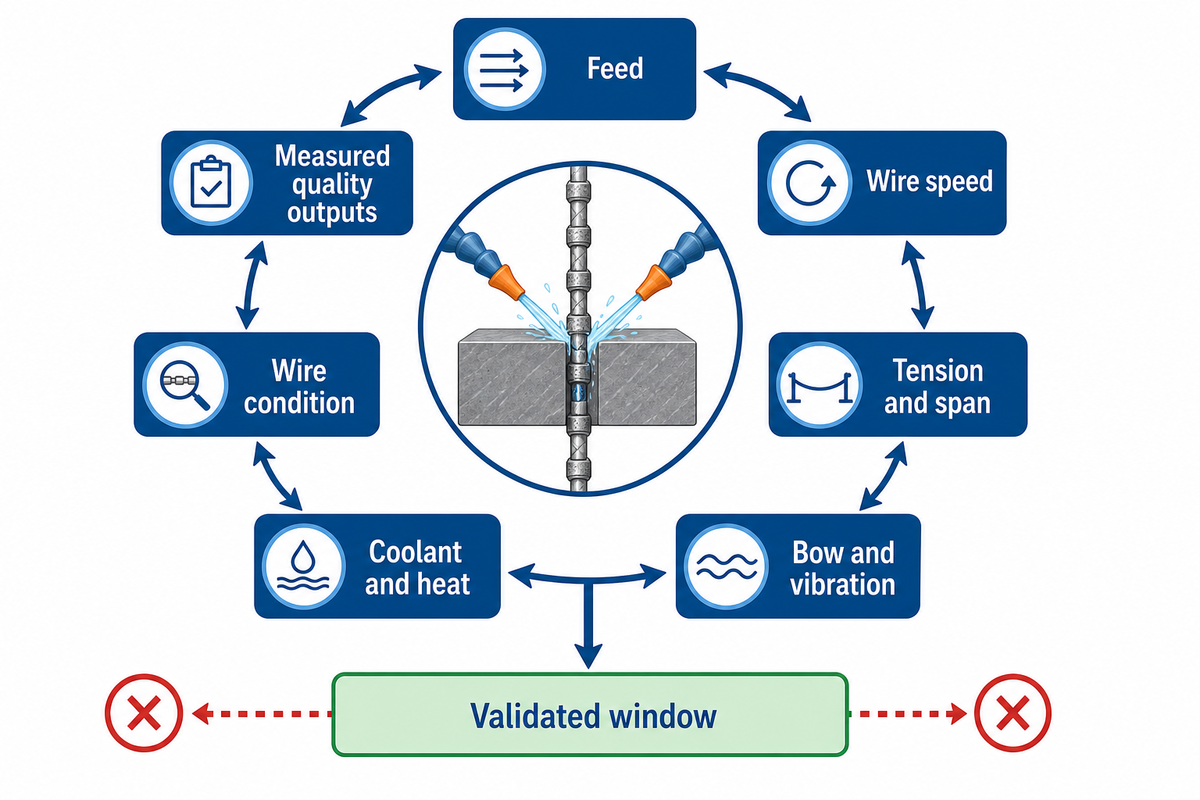
Elmasın tele yapıştırılması tel durumunu kesici takımın bir parçası haline getirir Besleme, tel hızı, gerginlik, açıklık, yay, soğutucu, kum maruziyeti, malzeme geometrisi ve aşınma artık etkileşime girer Bir değişkenin arttırılması, bir kurulumda çıkarmayı iyileştirirken diğerinde sapmayı, ısıyı, hasarı veya kırılmayı artırabilir.
Yararlı bir kontrol modeli kuvvet dengesi ile başlar Besleme iş parçasını telin içine iter Gerilim ve açıklık sapmaya karşı direnç gösterir Tel hızı kesme kontaklarını yeniler ve sıvı ve ısıyı taşır Kullanım sırasında elmas katmanı taneler aşındıkça, kırıldıkça, yüklendikçe veya kaybedildikçe değişir. Ortaya çıkan yay temas geometrisini değiştirir, bu nedenle “aynı” besleme komutu zaman içinde aynı yerel kesme koşulunu temsil etmeyebilir. Elmas tel testere kullanırken mühendisler, elmas tel testerenin nasıl çalıştığını, kesme sırasında oluşan ısıyı ve kesme parametrelerini optimize etmenin, yalnızca daha hızlı kesmeyi kovalamak yerine elmas tel kullanan ekipler için tutarlı kesme performansını nasıl koruyabileceğini belgeliyor.
Bu 2022 Frontiers aşınma modeli, tek topuzlu kuralların neden başarısız olduğunu göstermektedir. Modellenen aralıkları dahilinde, iş parçası beslemesi ve tel uzunluğu maksimum aşınmayı etkilerken, tel hızı, sallanma açısı ve ileri geri hareket sayısı nispeten az etkiye sahipti; iş parçası şekli aşınma profilini değiştirdi. Bu bir simülasyon sonucudur, bir çalışma spesifikasyonu değil, etkileşimi ve sınır bağımlılığını gösterir.
Bir NdFeB deneyi daha da keskin bir uyarı sağlar Yazarlar bunu yazdı gerilim 0,23 MPa'yı aştığında tel çok daha yüksek bir kopma riskine maruz kalır
. Bu eşik yalnızca bildirilen malzemeye, tele, makineye ve test kurulumuna aittir. Silikon, safir, grafit, seramik veya DONGHE makine tarifine kopyalanmamalıdır.
Parametre-pencere kontrol listesi
- Malzeme sınıfını, mikro yapıyı, yönelimi, boyutları, fikstürü ve gerekli kenar durumunu tanımlayın.
- Tam tel yapısını, çapını, kumunu, bağını, partisini, taze/kullanılmış durumunu ve seyahat düzenlemesini kaydedin.
- Çıktıları ölçün - tek başına komutları değil - gerçek döngü süresi, kerf, yay veya sapma, pürüzlülük, hasar, kırılma ve kabul edilen verim dahil.
- Örnek erken, istikrarlı ve daha sonraki yaşam kesimleri, böylece iyi bir deneme konumu tüm tel yaşam döngüsünü temsil etmez.
- Tedarikçi ve makine sınırları dahilinde her seferinde bir kontrollü faktörü değiştirin, ardından yayınlanmadan önce etkileşimleri onaylayın.
| Kanıt bağlamı | Bildirilen boyutlar veya ayarlar | Burada izin verilen kullanım |
|---|---|---|
| 2003 tarihli bir makalenin girişinde bildirilen tarihsel endüstri bağlamı | Giriş bölümünde 150 mm ve 200 mm'lik levhalar rapor edilmektedir; yaklaşık 0,30 mm ve 0,38 mm bıçak kerfi; ve tel, 300 mm'lik bir levha için 0,3 mm'nin altına yaklaşır | Makalenin kendi kerf deneyi değil, yalnızca ikincil tarihsel bağlam |
| NdFeB deneyi | Bu kurulumda 0,23 MPa'nın üzerinde daha yüksek kırılma riski rapor edildi | Arıza sınırı örneği, asla devredilebilir bir sınır değildir |
| Tek yönlü CFRP deneyi | 100 mm/dak ve 200 mm/dak besleme; 25 m/s ve 50 m/s kesme hızı; 7 mm, 14 mm ve 21 mm kalınlık; 2,4–3,4 μm ve 14,8–20,2 μm pürüzlülük aralıkları rapor edilmiştir | Malzeme yönelimi ve test koşullarının önemli olduğunu kanıtlayın |
| 2025 kerf kaybı raporu | 1.000–1.400 m/dakikada 350 μm tel | Son zamanlardaki titreşim ve yayılma araştırma sinyali, ultra ince telli bir tarif değil |
| Fraunhofer IKTS–PV Crystalox SliCer projesi | İnce taneli alümina için 10 μm/dakikada 4–8 mm sapma; yaklaşık 20 μm/dakikada küçük spinel sapması; 100 μm'nin altındaki disk potansiyeli | Katılımcı tarafından bildirilen, malzemeye özgü bulamaç karşı örneği |
| 2026 fotovoltaik-silikon incelemesi | 150 μm'nin altındaki levhalar ve 35 μm'nin altındaki teller | Sektörler arası bir spesifikasyon değil, kapsamlı görünüm |
| İncelenen destekli testere çalışması | Alıntılanan karşılaştırmasında 23.75% ortalama yüzey altı hasarı azalması | Yalnızca destekli süreç kanıtı |
| Resmi YARI MF657 mağaza kaydı | Görüntülenen revizyon geri çekilir ve yerine geçer | Yalnızca standart-durum kanıtı; Kabul testlerini belirtmeden önce geçerli belgeyi alın |
Kaynak sınırı: Her satır farklı bir malzeme, makine, tarih veya deneysel tasarıma aittir.Bu 2003 satırı açıkça makalenin girişinde bildirilen ikincil tarihsel bağlamdır.Bu değerler, çalışma ayarlarını önermek için değil, yanlış aktarımı önlemek için sunulmuştur.
Mekanizma derinliği için bkz elmas tel testere nasıl çalışır. Özel bir optimizasyon kılavuzu için mevcut olanı kullanın tel testere kesme parametreleri makale. Bu evrim sayfası, bu niyetlerle rekabet etmekten kaçınmak için kasıtlı olarak kontrol mantığında durur.
Anahtar paket servisi: Güvenli ayar, tanımlanmış bir malzeme, makine, kablo durumu ve kalite hedefi için doğrulanmış bir penceredir - başka bir uygulamadan kopyalanan bir sayı değildir.
Nesiller Boyunca Tel ve Kesme Makinesi Mimarileri
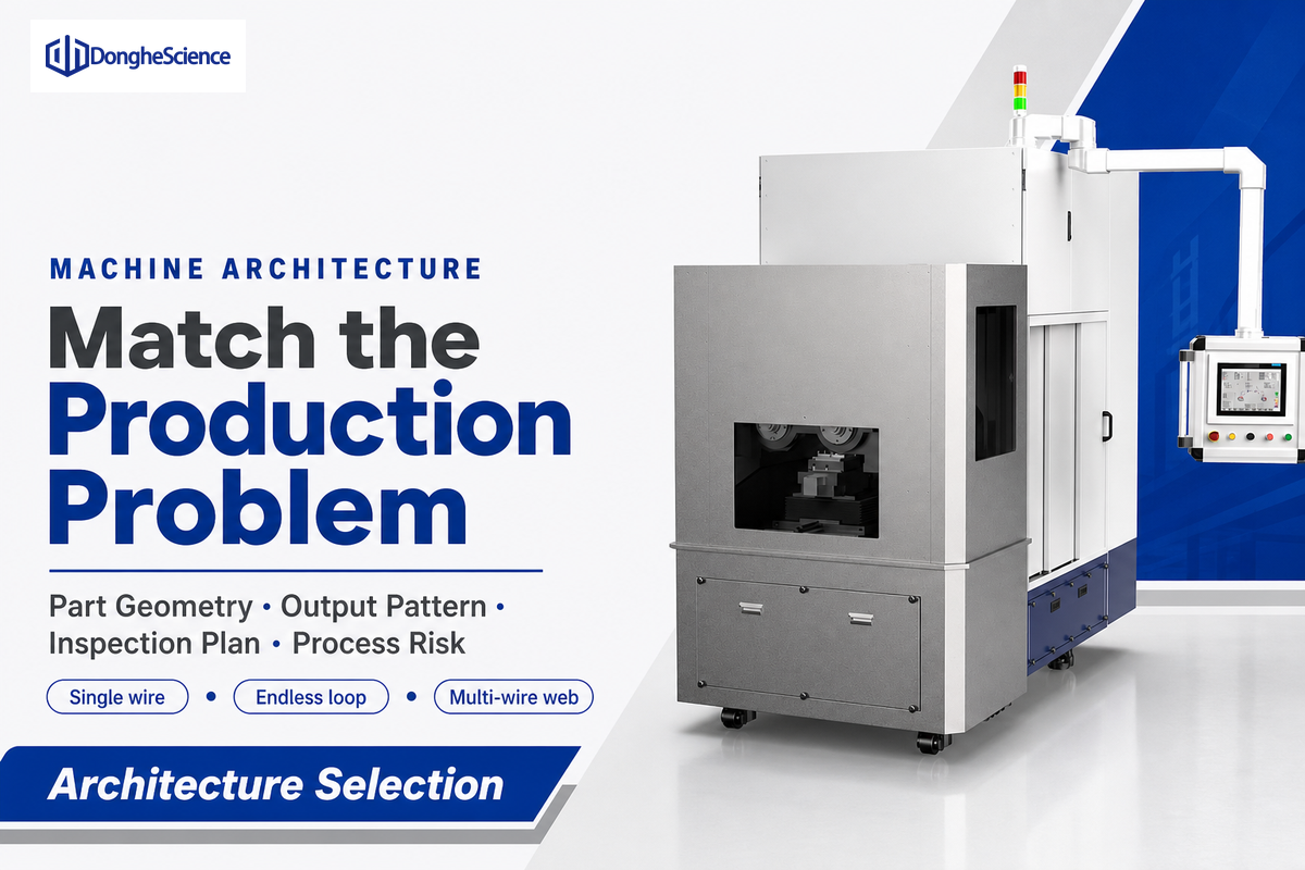
Doğru makine sınıfı üretim problemini takip eder. Laboratuvar numuneleri, silikon külçeler, oksit-seramik bloklar, grafit bileşenler ve betonarme aynı testerenin bir ölçekli versiyonunu gerektirmez. Hareket, tel depolama, parça erişimi, paralellik, sıvı kontrolü ve inceleme birlikte haritalanmalıdır.
- Tek telli hassas sistemler esnek geometriye, kurulum erişimine ve kontrollü bireysel kesimlere öncelik verin.
- Sonsuz döngü sistemleri sürekli hareket sağlar ve makaranın tersine çevrilmesini önler, ancak döngü üretimi, birleştirme, izleme ve değiştirme birinci dereceden kısıtlamalar haline gelir.
- Pistonlu veya makaralı beslemeli sistemler sonlu bir tel uzunluğunu yönetin ve işlem boyunca taze ve kullanılmış teli dağıtabilir.
- Çok telli sistemler paralel çıkışı hedefler ve kontrol edilmesi için ağ aralığı, sıvı dağıtımı, sapma ve alan boyunca tekdüzelik gerektirir.
- Boncuklu kablo sistemleri büyük kesitli taş, taş ocağı veya inşaat işlerini ele alın ve ayrı bir erişim, takviye, tahrik ve güvenlik analizi gerektirir.
DONGHE'nin birinci taraf yelpazesi, mimari tartışmalar için bir başlangıç noktası sağlar çok telli testere sistemleri. Ürün sayfaları mevcut makine ailelerini gösterebilir; tarihsel bir tarihi, evrensel bir yüzey sonucunu veya alıcının malzemesiyle uyumluluğu bağımsız olarak kanıtlayamazlar. Bunlar spesifikasyon incelemesi ve denemeleri gerektirir. Bir seçme elmas tel testere kesme makinası veya gelişmiş malzemeler için diğer kesme ekipmanları, tel testerenin türü, kesme malzemeleri ve gerekli kesme hassasiyeti ile başlar; elmas tel kesme makineleri daha sonra kılavuz düzeni, sıvı kontrolü ve çıkış düzeni bakımından farklılık gösterir.
Geleneksel kesme yöntemleriyle karşılaştırıldığında, bir elmas tel testere makinesi dar ve esnek bir kesme işlemiyle birden fazla malzemeyi ele alabilir, ancak sertlik tek başına sistemi seçmez.Sonsuz bir elmas tel düzeni, pistonlu hassas testere ve çok telli bir ağ, farklı izleme, erişim, çıkış ve inceleme gereksinimlerini zorunlu kılar.
Anahtar paket servisi: Makine modellerini karşılaştırmadan önce mimariyi parçadan, çıktı modelinden, inceleme planından ve süreç risklerinden kısa listeye alın.
Elmas Tel Teknolojisinin Nereye Taşındığı ve Bulamacın Hala Bağlama İhtiyacı Olduğu Yer
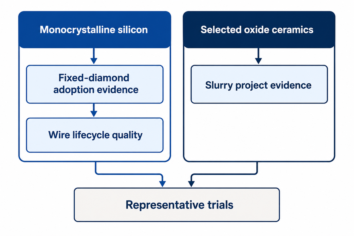
Sabit elmas tel silikon gofretleme ve diğer sert, kırılgan malzemelerde önemli hale geldi, ancak kanıtlar evrensel bir değiştirme hikayesini desteklemiyor. Malzeme tepkisi, ölçek, tel formatı ve aşağı akış gereksinimleri bir sonucu tersine çevirebilir. Hassas kaplamalı tel, bulamaç çoklu tel, sonsuz döngüler ve boncuklu kablo ayrı karşılaştırma şeritlerinde kalmalıdır.
Elmas tel testere teknolojisinin uygulamaları, hassas kesme sistemleri tarafından ele alınan belgelenmiş geniş malzeme yelpazesini kapsar ve elmas tel testereler, birkaçı arasında bir işlem seçeneği sunar; elmasla kesmenin herhangi bir avantajı uygulamaya özeldir ve malzeme ve kabul planına karşı kanıtlanmalıdır. Bu elmas aletler sert malzemelerin kesilmesini destekler, ancak ilgili kesme teknikleri ve kesme işlemleri otomatik olarak geleneksel kesimden daha iyi performans göstermez. Elmas tel evrensel bir kazanç sunmaz, bu nedenle elmas tel testereler yalnızca elmas aşındırıcılı tel bu gereksinimlere uyduğunda kullanışlı kesme performansı sağlar.
Silikon en net geçiş kanıtını sağlar. 2023 tarihli bir inceleme, sabit elmas teli monokristalin silikon levha kesimi için baskın yöntem olarak tanımlıyor. Yine de orada bile, 2016 silikon hasar çalışması yüzey özelliklerini külçe beslemesi, tel ileri geri hareket ve tel geçmesiyle ilişkilendirirken, hasar derinliği kum boyutu ve tel kullanımıyla ilişkilendirildi. Benimseme kalite sorununu sabit hale getirmedi.
Oksit seramik yararlı bir karşı örnek sağlar. Fraunhofer IKTS ve proje ortağı PV Crystalox, alümina, magnezyum alüminat spinel ve zirkonya içeren devam eden bir SliCer bulamacı çoklu tel projesini bildiriyor. İnce taneli alümina, dakikada yaklaşık 10 mikrometre hızla 4–8 mm tel alanı sapması üretti, oysa spinel, beslemenin iki katı hızla çok az sapma gösterdi. Katılımcı proje sayfası, eşit kalınlık ve düzlük zorluklarını işaretlerken 100 mikrometrenin altındaki diskler için potansiyel rapor ediyor.
Bu durum bulamacı genel olarak üstün kılmaz. Malzeme yapısının ve istenen alt tabakanın gevşek aşındırıcı araştırmaları alakalı tutabileceğini kanıtlıyor. Önerilen bir geçiş, kabul edilen verim, aşağı akış uyumluluğu, toplam döngü, sarf malzemeleri, sıvı kullanımı, stabilite ve ekonomi açısından onu geçemediğinde bir fabrika mevcut sürecini korumalıdır. -tek bir teknoloji “modern” etiket taşıdığı için değil.
Silikon dalı için DONGHE'nin silikon gofret kesme teli testere page birinci taraf çözüm bağlamı sağlar.Safir, silisyum karbür, grafit, teknik seramik, taş ve betonun her birinin kendi kanıtlarına ve makine sınıfına ihtiyacı vardır; silikon sonuçları otomatik olarak aktarılmamalıdır.
Anahtar paket servisi: Göç maddi ve amaca özgüdür; gerçek bir karşı örnek, evrensel iddiayı tersine çevirmek için bir neden değil, test etmek için bir nedendir.
5 Kapılı Geçişe Hazırlık Matrisi
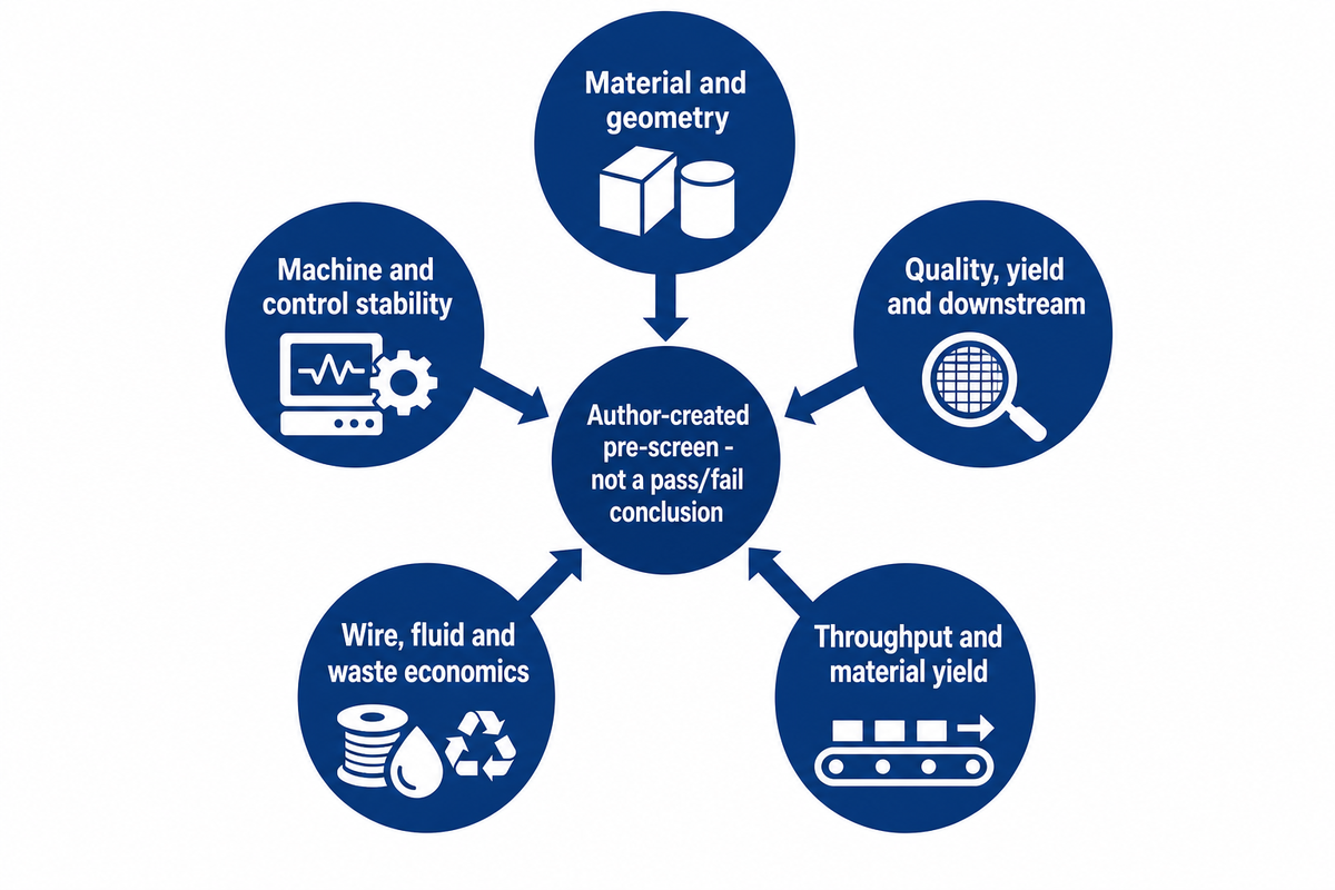
Bu beş kapılı matris, standart, sertifikasyon, doğrulanmış tahmin modeli veya DONGHE test sonucu değil, yazar tarafından oluşturulan bir mühendislik ön ekranıdır. Amacı, geniş bir “değişmeli miyiz?” tartışmasını alıcının sahip olduğu kabul kriterlerine dönüştürmektir. Yalnızca temsili denemeleri çizimi ve şu anda geçerli olan gereksinimleri karşılayan bir aday ilerler.
| Kapı | Soru | Talep edilecek kanıt | Gitme sinyali |
|---|---|---|---|
| 1. Malzeme ve geometri | Önerilen tel, bağ, makine, fikstür ve sıvı gerçek kaliteyi, yönü, boyutu ve özelliği kesebilir mi? | Temsilci kuponları ve parçaları; malzeme sertifikası; geometri haritası; fikstür ve erişim planı | Başka bir materyalden veya temsili olmayan bir kupondan ödünç alınan ayarlar |
| 2. Kalite, verim ve aşağı akış uyumluluğu | Kesilen parçalar çizim gereksinimlerini karşılıyor mu ve taşıma, tekstüre etme, bitirme, birleştirme, kaplama veya cihaz işlemede hayatta kalıyor mu? | Kerf, pürüzlülük, hasar, dalgalılık, düzlük, çözgü, kenar bütünlüğü, kırılma, verim ve duruma göre aşağı yöndeki test sonuçları | Aşağı yönde veya verim kanıtı olmayan, güzel görünümlü bir kesim |
| 3. Verim ve malzeme verimi | İşlem, en yüksek kesme hızı yerine kabul edilen çıktıyı iyileştiriyor mu? | Saatte iyi parçalar, toplam döngü, kurulum, temizleme, durdurma, yeniden işleme, kerf dağıtımı ve malzeme verimi | Kabul edilen parça muhasebesi olmayan bir tepe hız rakamı |
| 4. Tel, sıvı ve atık ekonomisi | Sarf malzemeleri ve taşıma maliyetleri planlanan kablo ömrü boyunca istikrarlı mı? | Kabul edilen parçaya göre tel kullanımı; alıştırılmış, stabil ve daha sonraki yaşam numuneleri; sıvı, filtreleme, kullanılmış tel, ince taneler, temizleme ve imha kayıtları | Atık ve geri kazanım kalitesini hariç tutan tek kesim deneme veya maliyet modeli |
| 5. Makine ve kontrol stabilitesi | Makine gerekli pencereyi tutabilir ve kusurlar kaçmadan önce sürüklenmeyi ortaya çıkarabilir mi? | Gerilim ve yük eğilimleri, yay veya sapma, titreşim, alarmlar, tel kopma olayları, kalibrasyon, bakım ve yetenek kanıtları | Trend verisi yok, açıklanamayan sapma yok veya belgelenmemiş operatör ayarlamasına bağımlılık yok |
Standart uyarısı: MF657 için incelenen resmi SEMI mağaza sayfası görüntülenen revizyonu geri çekilip yerine koymuştur.Bu nedenle burada güncel bir gereklilik olarak sunulmamaktadır. Alıcılar geçerli çizimi, müşteri özelliklerini veya standardı adlandırmalı ve nitelikli personele sürümü ve yöntemi onaylatmalıdır.
Matris RFQ'ya nasıl dönüştürülür
- Parça çizimini, malzeme spesifikasyonunu, miktar desenini ve gelen koşulu takın.
- Kesimin geçmesi gereken aşağı yönlü testleri de içeren gerekli çıktıları ve inceleme yöntemini tanımlayın.
- Deneme için önerilen tel konstrüksiyon, sıvı, fikstür, makine mimarisi ve kontrollü menzili tedarikçiden isteyin.
- Her kablo ömrü aşamasında deneme örnek boyutunu tanımlayın ve durdurmaların, kırılmaların, yeniden çalışmaların ve reddedilenlerin nasıl sayılacağını önceden kabul edin.
- Kabul edilen toplam parça ekonomisini karşılaştırın ve belgelenmiş bir mevcut süreçle kalma dalına sahip olun.
Deneme sınırı tanımlandıktan sonra, gözden geçirin elmas tel kesme makinası serisi ve DONGHE'den uygulamayı bir makine sınıfına eşlemesini isteyin. Her sabit aşındırıcı sistemin daha hızlı olacağına dair desteklenmeyen bir söz değil, kanıt bir sonraki doğru adım olmaya devam ediyor.
Anahtar paket servisi: Matris yapıları soruları; alıcının çizimi, mevcut gereksinimleri ve zamana göre dağıtılan deneme verileri hazır olma durumunu belirler.
2026'da Neler Değişiyor: Ultra İnce Tel, Daha İnce Gofretler ve Daha Dar Proses Penceresi
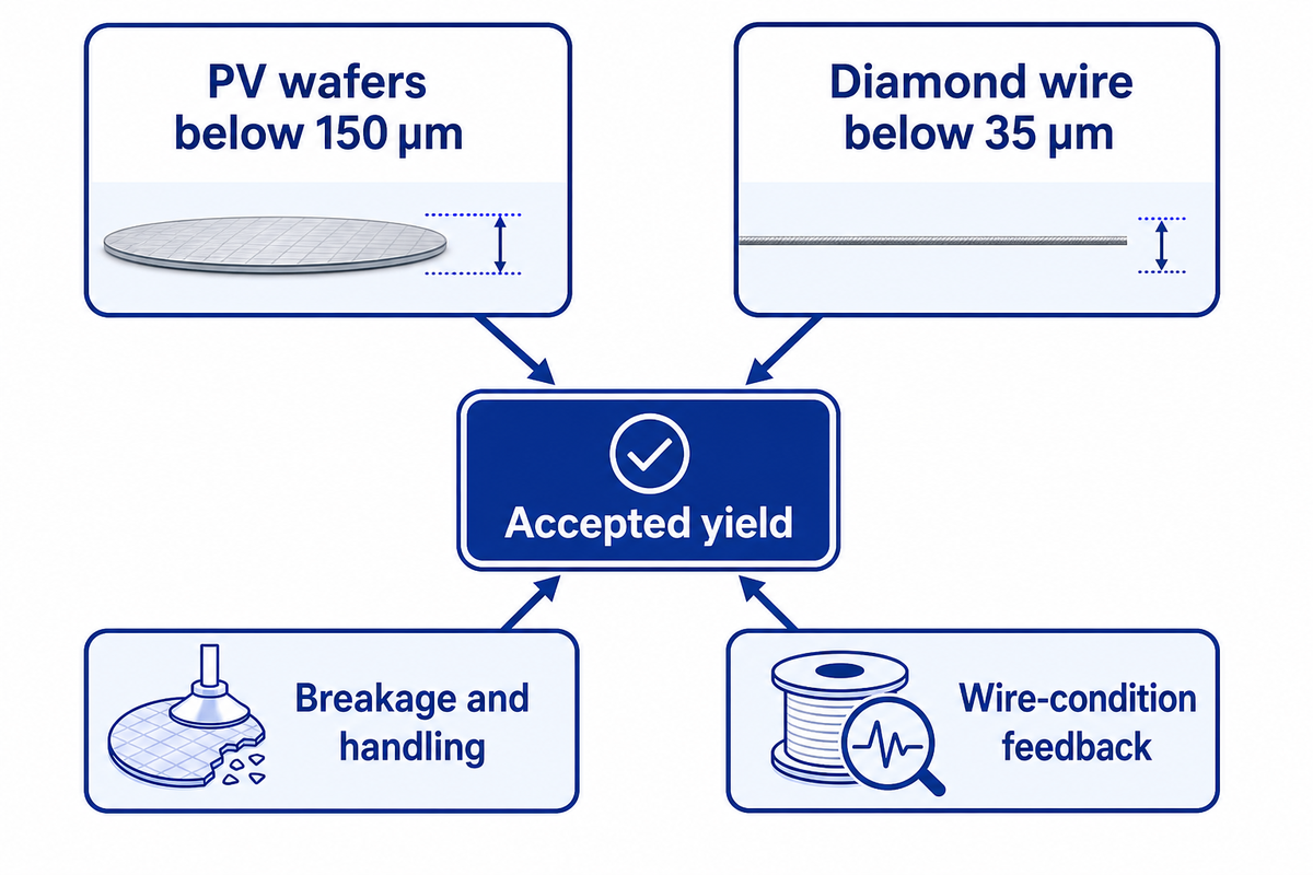
2026'da fotovoltaik silikonda sınır sadece daha yüksek tel hızı değil; hem levha hem de tel verim kaybı olmadan inceldikçe bir külçeden daha fazla satılabilir levha kazanıyor. Bu yön, kırılma, testere izleri, çözgü, aşınma, yol tutuşu ve tel fiyatı daha hassas hale geldikçe süreci daha düşük kerf'e doğru itiyor.
A 2026 hakemli akademik – endüstri incelemesi i̇lgili fotovoltaik-silikon geliştirme basıncını 150 mikrometrenin altındaki levhalar ve 35 mikrometrenin altındaki elmas tel olarak tanımlar.Yazar bağlantıları arasında JIER Machine-tool Group ve Qingdao Gaoce Technology yer alır, dolayısıyla tamamen bağımsız bir akademik görüş olarak sunulmaz. Bu eşikler safir, grafit, oksit seramikler, laboratuvar numuneleri, taş veya beton için spesifikasyonlar değildir. Silikon malzeme verimi basıncının ne kadar ileri gittiğine dair kapsamlı bir sinyaldir.
| Yön | Potansiyel kazanç | Yeni kısıtlama | Alıcı imajı |
|---|---|---|---|
| Daha ince fotovoltaik-silikon levha | Külçe başına daha fazla levha ve levha başına daha düşük silikon kullanımı | Daha yüksek kullanım hassasiyeti, kırılma riski ve warp tepkisi | Kesim sonrası taşımayı ve aşağı yöndeki verimi kabul planına dahil edin |
| Daha ince elmas tel | Alt teorik kerf | Daha az tel kesiti, daha hızlı aşınma hassasiyeti ve daha fazla kırılma sonucu | Örnek kalitesi ve tel kullanımı, çalışma boyunca, tek bir sabit noktada değil |
| Daha yüksek kullanım basıncı | Kabul edilen levha başına daha düşük malzeme maliyeti | Küçük kusurlar, reddedilme yoluyla kerf kazancını silebilir | Nominal dilim sayımına değil, kabul edilen verime öncelik verin |
| Daha sıkı hareket kontrolü | Potansiyel olarak daha iyi tutarlılık ve daha erken sürüklenme tespiti | Titreşim, açıklık, yay, ters çevirme ve sensör yorumlama etkileşimi | Ölçülen kaliteye bağlı trend verilerini ve alarm mantığını gerektirir |
Kaynak ve kapsam: Ge ve ark. (2026) fotovoltaik-silikon eşikleri ve kısıtlamaları için; PV Magazine (2025) yanal titreşim ve aşırı kerf araştırması hakkında yakın tarihli bir rapor için. Bildirilen çalışmada ultra ince sınırdan çok daha büyük tel kullanıldı, bu nedenle koşullar tek bir tarifte birleştirilmedi.
Buna göre, seyahat yönü daralan marjlar altında hassasiyettir.Daha iyi algılama, tel-koşul takibi, akışkan kontrolü ve kalite geri bildirimi nominal hız kadar önemli olabilir.Daha ince tel, yalnızca sistemin geri kalanı bu teli -ve giderek kırılganlaşan kısmı- istikrarlı, incelenebilir bir pencerenin içinde tutabildiğinde değer yaratır.
Anahtar paket servisi: Ultra ince tel bir sistem sorunudur: Daha düşük kerf yalnızca verim, kullanım, yüzey bütünlüğü ve tel ömrü kontrol altında kaldığında değere sahiptir.
Sıkça Sorulan Sorular
Bu cevaplar genel prensipleri uygulamaya özel ayarlardan ayırır Bir alıcının bir sonraki mühendislik tartışmasını çerçevelemesine yardımcı olabilirler, ancak malzeme çizimi, tel spesifikasyonu, makine kılavuzu, risk değerlendirmesi veya kalifiye personel tarafından incelenen temsili bir denemenin yerini alamazlar.
Elmas tel kesme yöntemi nedir?
Elmas tel kesme, elmas aşındırıcı taşıyan bir teli bir iş parçası boyunca hareket ettirirken kontrollü besleme kesimi oluşturur. Elmas elektrolizle kaplanabilir, reçineyle bağlanabilir, lehimlenebilir, sinterlenebilir veya boncuklara yerleştirilebilir ve tel sonsuz bir döngü, ileri geri hareket eden uzunluk, makara beslemeli yol veya çok telli ağ olarak çalışabilir. Soğutucu veya kesme sıvısı ısıyı ve döküntüleri giderirken gerilim, yay, hız, besleme, tel durumu ve malzeme tepkisi gerçek sonucu belirler. Bu nedenle evrensel bir kurulumdan ziyade bir süreçler ailesidir. Seçmeden önce iş parçasını, tel yapısını, hareketi, inceleme yöntemini, gerekli kenar ve yüzey durumunu, kabul edilen verimi ve aşağı akış işlemlerini tanımlayın. Malzeme denemeleri, tel durumu değiştikçe bu gereksinimlerin sabit kaldığını doğrulamalıdır.
Elmas tel testerelerin faydaları nelerdir?
Eşleştirilmiş bir uygulamada, elmas tel testere dar kerf, kontrollü kesme kuvvetleri, esnek parça erişimi ve sert veya kırılgan malzemelerin verimli bir şekilde kesilmesini sağlayabilir.Sabit aşındırıcı ayrıca dolaşımdaki gevşek aşındırıcı karışıma bağımlılığı azaltabilir. Faydaları kabul edilen çıktı olarak ölçülmelidir, ancak.Tel aşınması, kırılma, yüzey hasarı, sıvı kullanımı, aşağı akış uyumluluğu, kurulum süresi ve makine stabilitesi nominal bir hızı veya kerf avantajını dengeleyebilir.
Elmas tel testere ne kadar hızlı kesilebilir?
Sorumlu evrensel hız yoktur Kesme oranı malzemeye, kesite, tel konstrüksiyonuna ve çapına, elmas boyutuna ve bağına, makine sertliğine, kılavuz açıklığına, gerilime, tel hızına, besleme stratejisine, sıvıya, istenen yüzey durumuna ve tel ömrüne bağlıdır. Yüksüz bir tel hızı rakamı veya başka bir malzemeden bir tepe beslemesi değil, tanımlanmış bir kabul planı altında saat başına iyi parçaları karşılaştırın. Tedarikçiler bir deneme penceresi önermeli ve koşulları belgelemelidir.
Elmas tel testere ne kadar dayanır?
Tel ömrü bağ, kum maruziyeti, tel çapı, malzeme aşındırıcılığı, bağlantı uzunluğu, hız, besleme, gerilim, sıvı, kirlenme ve kabul edilebilir kalite ile değişir.kabul edilen parça başına tüketilen tel izleyin ve erken, istikrarlı ve daha sonraki yaşam kesimlerini inceleyin.Makine, malzeme, tel spesifikasyonu, durdurma kuralı ve kalite sınırı olmayan uzunluk veya saat rakamları aktarılamaz.
Sonsuz tel ile makara üzerindeki tel arasındaki fark nedir?
Sonsuz bir tel, kılavuz tekerleklerin etrafında sürekli olarak dolaşan kapalı bir döngüdür.Makara veya pistonlu sistemler, sonlu bir tel uzunluğunu yönetir ve süreç boyunca yönü tersine çevirebilir veya taze teli dağıtabilir. Daha iyi seçim, kesme geometrisine, izlemeye, ters çevirme etkilerine, kullanılabilir tel uzunluğuna, gerilim kontrolüne, değiştirme yöntemine, verim modeline ve tedarikçinin doğrulanmış tel seçeneklerine bağlıdır.
Elmas tel bulamaç testerenin yerini tamamen aldı mı?
Hayır. Sabit elmas tel, önemli silikon levha bağlamlarında baskın hale geldi, ancak değiştirme malzemeler ve ölçekler arasında evrensel değildir. Fraunhofer IKTS ve proje ortağı PV Crystalox hala seçilen oksit seramikler için bulamaç çoklu tel araştırmasını rapor ediyor. Önerilen alternatif kalite, aşağı akış uyumluluğu, verim, verim, tel ömrü, sıvı kullanımı, stabilite ve temsili iş parçaları üzerindeki ekonomik kriterleri karşılayamadığında bir alıcı mevcut süreci korumalıdır.
Şeffaflık ve İnceleme Notu
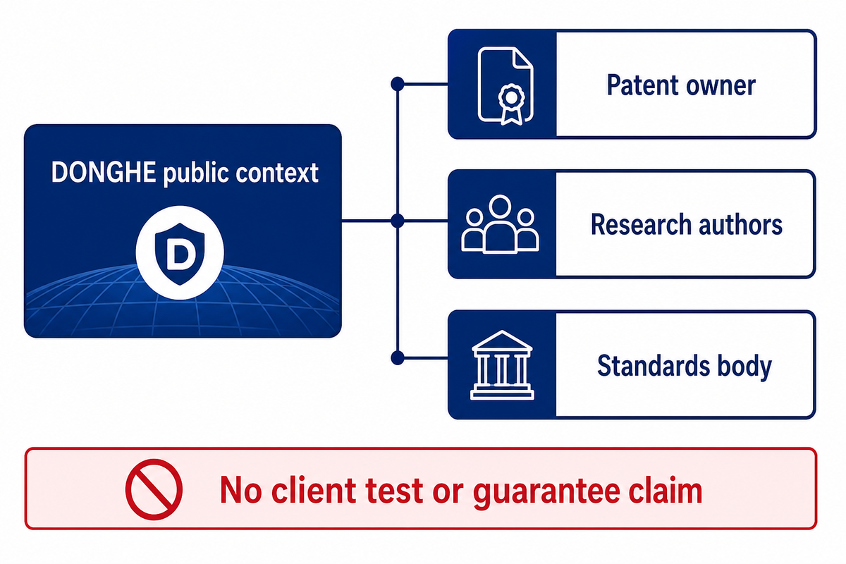
Yazar: DD. Bu makale Shanghai Donghe Science & Technology Co., Ltd. (DONGHE) için hazırlanmış ve kamuya açık akademik, resmi, patent ve endüstri kaynaklarına göre incelenmiştir. DONGHE'nin halka açık şirketi ve ürün sayfaları birinci taraf üretici bağlamı sağlayın; belirtilen üçüncü taraf araştırması, orijinal sahiplerine atfedilmeye devam eder Müşteriye ait hiçbir test veri seti, müşteri sonucu, sertifika veya evrensel süreç garantisi talep edilmez.
Makineyi Seçmeden Önce Denemeyi Tanımlayın
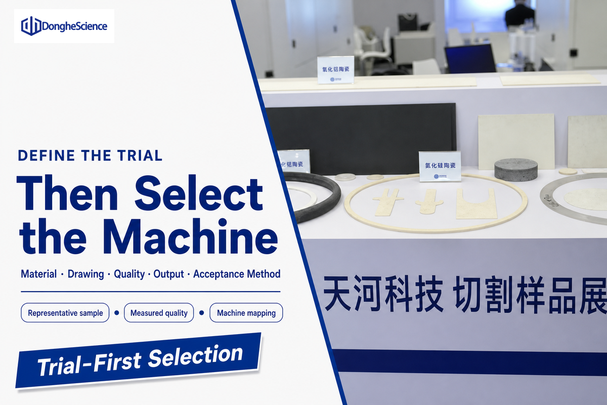
DONGHE'ye malzeme, çizim, boyut, hedef kalite, çıktı modeli, mevcut süreç ve temsili, ölçülebilir, uygulamaya özel bir deneme için kabul yöntemini gönderin. Mühendislik tartışması daha sonra genel bir hız vaadi yerine doğru tel ve makine mimarisiyle başlayabilir.
Referanslar ve Kaynaklar
- Barron, LH. US3150470A: Elmas Kaplı Tel Testere, öncelik 1961, 1964'te yayınlandı. Yalnızca patent önceki teknik kanıtı.
- Clark, WI, Shih, AJ, Hardin, CW, Lemaster, RL ve McSpadden, SB. Sabit aşındırıcı elmas tel işleme, bölüm I: süreç izleme ve tel çekme kuvveti, 2003.
- Li, A. ve ark. Hassas Elmas Tel Testere Monokristal Silikonunda Son Gelişmeler, 2023.
- Ge, P. ve ark. (akademik ve endüstri ortak yazarları). Ultra ince elmas tel kullanılarak ince yarı iletken levhaların dilimlenmesinde ilerleme ve kritik zorluklar, 2026.
- Seeholzer, L. ve ark. Tek yönlü CFRP'nin elmas tel testereyle kesilmesinde işleme özelliklerinin deneysel olarak araştırılması, 2021.
- Yang, Z., Huang, H. ve Liao, X. Pistonlu hareketle çok telli sallanan testere sırasında kesme parametrelerinin elmas telin aşınması üzerindeki etkisi, 2022.
- Rockies Ulusal Laboratuvarı araştırma kaydı. Silikon Güneş Pilleri için Elmas Tel Kesilmiş Gofretlerin Yüzey Özellikleri ve Hasar Dağılımları, 2016.
- Fraunhofer IKTS ve PV Crystalox (SliCer projesi). Yüksek performanslı oksit seramik alt tabakalar için verimli çok telli testere işlemi, katılımcı proje sayfası.
- PV Dergisi. SolarWorld, Alman gofretleri için elmas tel testerelere yatırım yapıyor, 2017. Şirket duyurusuna dayalı ticaret raporlaması.
- PV Dergisi. Güneş gofret üretiminde kerf kaybını azaltmak için elmas tel testereyi geliştirmek, 2025. Bir araştırma çalışmasına ilişkin ticaret raporlaması.
- YARI. MF657 ürün ve durum sayfası. Görüntülenen bu revizyon geri çekilmiş ve değiştirilmiştir olarak işaretlenmiştir.
![Polisilikon Malzeme: Özellikler, Sınıflar ve Kullanım Alanları [Kılavuz]](https://wiresawcutter.com/wp-content/uploads/2026/08/polysilicon-material-featured-768x512.webp "Polisilikon Malzeme: Güneş ve Yarı İletken Endüstrilerinde Özellikler, Sınıflar ve Kullanım Alanları 15")
![Polisilikon Malzeme: Özellikler, Sınıflar ve Kullanım Alanları [Kılavuz]](https://wiresawcutter.com/wp-content/uploads/2026/08/polysilicon-material-featured-150x150.webp)