DONGHE Company に連絡してください


2026年6 月更新 ・ 上海東河科学技術技術チームによるレビュー
A 炭化 ケイ素 発熱体 は、大部分が再結晶炭化ケイ素 (SiC) で作られ、金属線が生き残ることができる温度をはるかに超えた温度で電流を輻射熱に変換する非金属セラミック抵抗器です。キルン、熱処理炉、ガラスタンク、または高温実験炉を稼働させる場合、SiC 要素はホットゾーンの背後にある主力となることがよくあります。このガイドでは、これらの要素とは何か、熱の発生方法、形状と仕様の選択、経年劣化に伴う抵抗の挙動がなぜそれほど奇妙であるか、配線方法とサイズ設定、需要の方向について説明します。.
炭化ケイ素発熱体は、約 1625° C (2957° F) までの素子温度で電流を輻射熱に変換する再結晶化された SiC セラミック ロッドまたはチューブです。金属素子とは異なり、その電気抵抗は経年変化とともに永続的に上昇し、以下のほぼすべての設計と配線ルールを駆動します。.
速いスペック: ケイ素の炭化物の発熱体
| 材料 | 再結晶/反応結合したアルファ炭化ケイ素 (SiC) |
| 最大要素 (表面) 温度 | ~1625° C (2957° F)まで; 長寿命のための~1550° C |
| 典型的な炉の範囲 | 600 ~ 1600° C、空気または多くの制御された雰囲気 |
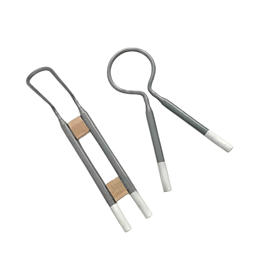
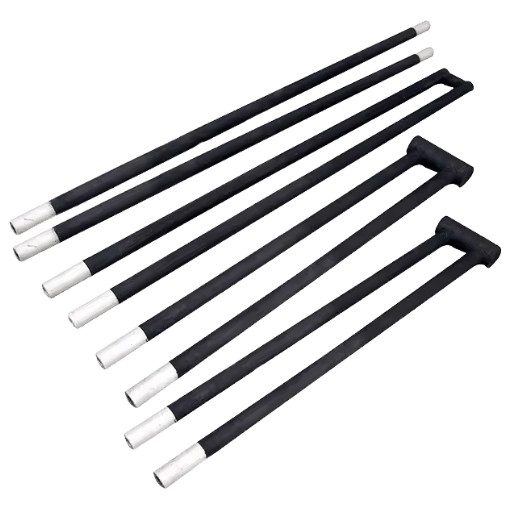
| フォーム | ロッド、チューブ、シングル/ダブルスパイラル、U、ダンベル、三相 |
| 直径/長さ | 0.5 ~ 3 インチ (10 ~ 55 mm) / 1 ~ 10 フィート (約 6 m) |
| 抵抗行動 | 年齢とともに上昇します(平行配線+マッチドセット交換を駆動します) |
| 耐用年数終了マーカー | 抵抗は元の値から~3×に達します |
💡 主なポイント
- SiC 素子抵抗は、ほとんどの人がヒーターの動作を期待しているのとは逆に、経年劣化とともに不可逆的に上昇します。.
- 下面ワット荷重 (W/cm²) は、耐用年数における単一の最大のレバーです。.
- 要素を並列に配線し、一致するセットとして置き換えます。古いバンクに新しい要素を 1 つドロップすることはありません。.
- SiC は約 600 ~ 1600°C を所有しています。それを超えると二ケイ化モリブデンが引き継ぎます。.
炭化ケイ素発熱体とは何ですか?
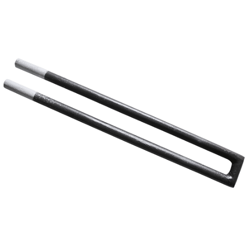
炭化ケイ素発熱体は、主に再結晶化された炭化ケイ素 (SiC) から作られた非金属の高温セラミック抵抗器であり、形成されてから高密度のロッドまたはチューブに再結晶化され、約 1625° C までの元素温度で電流を輻射熱に変換します。これは、これらの元素がキルン、ガラスタンク、熱処理炉を駆動する理由です。.
カーボランダムとも呼ばれる炭化ケイ素自体は、モース硬度で 9 を超えるシリコンと炭素の化合物であり、ダイヤモンドの硬度に近いため、金属ヒーターが溶けたり垂れ下がったりする場所でも生き残ります。ほとんどの元素は再結晶化した SiC を使用しますが、スパイラル ホット ゾーンは反応結合した炭化ケイ素から作られることが多く、密度が高くなります。.
2 つの構造ファミリーが優勢です。再結晶化された SiC は、中央のホット ゾーンと 2 つのクーラー エンドを備えたクラシック ロッドを提供します。スロット付きスパイラル要素で使用される反応結合型 SiC は、より小さな断面に対してより高い密度をパックします。同じ硬くて脆い SiC ファミリーが、ハイテク精密作業全体から現れます 炭化 ケイ素 研磨剤 ダイヤモンド ワイヤー ソー スライスをインゴットに粒状にします。米国国立標準技術研究所によると、再結晶化された SiC (Globar) ロッドは、次のような役割を果たすのに十分な頑丈さと耐酸化性がありました 二次赤外線放出規格, 、材料が赤熱でどれだけ安定しているかを示す有用なヒント 化学と結晶の背景については、の概要を参照してください 炭化ケイ素 wikipediaより.
その硬度の1 つの実用的な結果: SiC要素は壊れやすく、不用意にノックまたはクランプされた場合に亀裂が入りやすい、SiCインゴットを切断したことがある人なら誰でもすぐに学習できる特性である実際には、亀裂のある要素は新しい炉で最も一般的な保証問題であり、それが設置時に精密粉砕されたコールドエンドと約±0.5 mmの厳しい直径許容誤差をもたらす理由です。セラミック材料として、SiCはセラミックとしては比較的高い導電性に加え、強力な酸化と耐食性、低い変形、そして使用中の最も厳しい発熱体セラミックスの1 つとなる耐久性を提供する最も有名なブランドであるKanthalのGlobarラインは、再結晶化されたSiCを高温電気炉のデフォルトにするのに役立ちました。.
炭化ケイ素発熱体がどのように熱を発生させるか

ジュール加熱による SiC 素子の熱: 電流が素子を通過し、その電気抵抗を満たし、その電力が熱になり、W = I²R に従います。W はワット単位の電力、I は電流、R は抵抗です。この素子は、その中央のホットゾーンが高い抵抗で走って光る形状になっており、2 つの冷却器の端は低い抵抗を持ち、炉壁を横切る場所では冷たく保たれます。.
エンジニアはこれらのコールドエンドにアルミニウム処理を行い、特許取得済みのアプローチの 1 つは、特にコールドエンドの断面を拡大します 下端抵抗 そしてその熱をチャンバー内に保ちます そのホットゾーンとコールドエンドの比率を間違えて、端が過熱し、それが壁から離れる場所に要素をひび割れる故障 エンジニアは、ほとんどの初期の故障の根本原因がホットゾーンではなく、過熱したコールドエンドであるため、比率をサイズ設定します; 1400° Cで24 時間稼働する生産炉は、不一致を罰します。.
炭化ケイ素発熱体はどのように熱を発生させるのでしょうか?
炭化ケイ素発熱体は抵抗的に熱を発生します。高抵抗の SiC ホット ゾーンには電流が流れ、材料はその電気エネルギーを輻射熱として放散します。ホットゾーンの抵抗率は大きく、表面が約 1050° C に達すると約 600 ~ 1400 オーム mm²/m になるため、適度な電流であっても激しく均一な輻射熱を生成します。.
抵抗は一定ではありません: 室温から約800° Cまでそれは落ちる (負の係数) 、その後800° Cを超えると、温度 (正の係数) で再び上昇し、その間のどこかに最小に達するこのU字型の曲線は、炉制御システムが飼いならさなければならない最初の奇抜なものです。.
炭化ケイ素が空気中で加熱されると、ゆっくりと酸化します。この反応は元素の生命の中心的な物語となり、以下で説明します。ここでの酸化物の成長は、たとえば米国エネルギー省の研究など、表面科学レベルで研究されています 炭化ケイ素の酸化.
種類と形状: ロッド、スパイラル、ダンベル、U エレメント
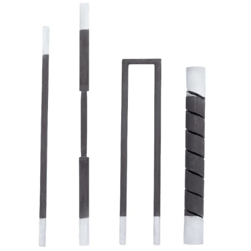
要素の形状は、炉の形状、配線レイアウト、必要なホットゾーン表面の量に合わせて選択されます。 6 つのファミリーがほぼすべての炉をカバーします:
| タイプ | フォーム | のためのベスト |
|---|---|---|
| ED(ロッド) | まっすぐな棒、熱い地帯+ 2 つの冷たい端 | 一般的な箱型および管型炉 |
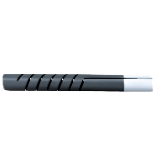
| SC(シングルスパイラル) | スパイラルスロットホットゾーン | より短い長さでより高い抵抗 |
| SG(単一螺旋、反作用-結合される) | 高密度スパイラルホットゾーン | 雰囲気の軽減または腐食性 |
| SCR(ダブルスパイラル) | 両端子とも一端 | シングルエンド配線、タイトなチャンバー |
| SGR(ダブルスパイラル、リアクションボンド) | 高密度、シングルエンド端子 | コンパクトな高耐久チャンバー |
| Uタイプ | 2 本の脚をヘアピンに接合しました | 片側の両方の接続 |
| DB(ダンベル) | 拡大されたコールドエンド | 端部損失が少なく、炉壁の加熱が少なくなります |
| スロット (Ux) | スパイラル溝付き加熱セクション | 腐食しやすい厳格な義務 |
| LD | 長いコールドエンドロッド | 厚い炉の壁、深いターミナル |
| W(三相) | マルチレグ | 三相炉バンク |
間違った形状を選択するのは高価な間違いです: あまりにも長いロッドは、炉壁の内側にホットゾーンの一部を残し、そこで過熱して亀裂します 実際には、航空宇宙および自動車熱処理店は、壁の損失をカットするために、拡大された30 mmの冷たいセクションでダンベルエンドを好む一般的なサイズは、直径0.5 から3 インチ (10 から55 mm) 、長さ1 から10 フィートで、ホットゾーンはおよそ4.2 mまであります サプライヤーは、構成、直径、長さをカスタマイズします 螺旋スロットタイプUヘアピンを含む、炉に一致する単一螺旋要素のスパイラルスロットは装飾的ではないことに注意してください: それはその抵抗を上げ、中心に対して端を冷たく保つホットゾーンの断面積を減少させる、初期に形式化されたアプローチ 炭化 ケイ素 素子 特許.
温度範囲と主要仕様
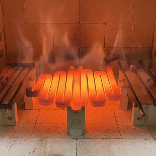
炭化ケイ素は耐熱性がありますか? 非常に. SiC発熱体は、約1625° C (2957° F) までの素子表面温度で動作し、ほとんどの炉は連続600 から1600° Cで動作しますしかし、見出し番号は天井であり、巡航速度ではありません: 1600° C付近で素子を連続的に実行すると、耐用年数を高速に交換することになるため、多くの設計者は、ヘッドラインの最大動作温度ではなく、およそ1550° Cを高品質素子の実用的な長寿命天井として扱います。 SiCは赤熱で有用な強度と耐酸化性を維持するため、の研究が行われています 高温サービス用SiC パデュー大学では、その強度保持と高い熱伝導率を強調しています。.
| 財産 | 典型的な値 |
|---|---|
| 最高表面温度 | ~1625° C (2957° F) |
| 比重 | 2.6~2.8g/cm3 |
| 空隙率 | <30% |
| 曲がる強さ | >300kg; 25° Cで約50MPaの破裂 |
| 熱伝導率(1000° C) | 14~19 W/m・°C |
| 放射率(放射率) | 0.85 |
公開されているSiC要素データからコンパイルされた値; 特定のグレードについて、サプライヤのデータシートに対して確認します。.
嬴工注
混同される2 つの数字を分けてください: 素子表面温度と炉 (チャンバー) 温度です。 素子から負荷に熱が流れるため、素子は常にチャンバーよりも高温で動作します。 1600° Cのチャンバーは、素子表面温度をその上方まで押し上げる可能性があるため、チャンバー温度が上昇すると、表面負荷テーブルがキャップワット密度を下回ります。.
炭化ケイ素発熱体が使用される場所
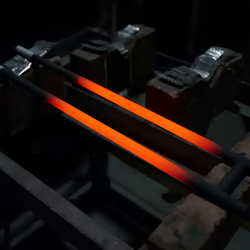
SiC 要素は、プロセスが必要な空気中または制御された雰囲気中でのクリーンで電気的な高温熱、セラミック焼成、ガラスの溶融と成形、金属熱処理、冶金と分析、粉末冶金、磁性材料焼結、廃棄物焼却、自動車部品の熱処理など、あらゆる場所で使用されます。実験室やパイロット炉も固定します。.
すべてのアプリケーションにリスクが伴います: 要素数を節約するには要素を熱くしすぎて、数ワットの耐用年数を交換します。たとえば、1500° C を保持する医療用セラミック窯は、表面荷重が遅延していない場合、要素を高速に亀裂します。米国エネルギー省は、次のように述べています 工業プロセス熱 産業用エネルギー使用量の最大のスライスであるため、これらの炉の背後にある要素はプラント規模で重要です。.
半導体は、SiC素子の成長が早いホームです, 電源チップを作る同じ高温拡散, 酸化, そして焼結のステップは、正確に1200 1600° Cバンドで実行するため SiCが所有する: メーカーのより硬い原料をスライスするための広範なプッシュに素子を直接結び付けること SiC ウェーハ 切断 設備 および 硬くて脆い材料の切断 ラインは同じサプライチェーンに供給します。 advancedからの脆い非金属ワーク セラミックス ダイヤモンド ワイヤーソー 光学ブランクの加工は、これらの元素の熱と同じ炉に依存します。.
SiC vs MoSi2 vs 金属元素: 1625° C クロスオーバー ウィンドウ
炭化ケイ素にはどのような欠点がありますか? ほとんど2 つ: 抵抗の年齢、そしてその天井は高いものの、利用可能な最高ではありません そこで、元素ファミリー間の選択が来るのです 私たちはその決定を と呼びます 1625° C クロスオーバー ウィンドウ: 見出し番号が最も大きい要素ではなく、実際の動作温度と雰囲気をスイートスポットで囲む要素を選択します。.
| エレメント | 実用的なマックス | 年齢による抵抗 | いつそれを選ぶか |
|---|---|---|---|
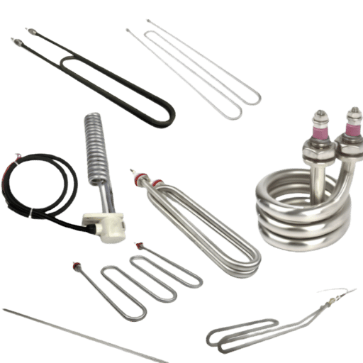
| FeCrAl / NiCr ワイヤー | ~1200~1400° C | ゆっくりと上昇 (NiCr) / 安定 | 低温、最低コスト |
| 炭化ケイ素(SiC) | ~1600~1625° C | 人生を超えて約3×上昇します | 600 ~ 1600° C、サイクリング、コスト重視 |
| 二ケイ化モリブデン (MoSi2) | ~1800~1900° C | 安定して推移 | ~1600° C の上、酸化 |
温度帯は典型的です;グレードデータシートに対して検証します。.
直観に反する部分は次のとおりです. 二ケイ化モリブデン sicよりも熱くなり、批判的に言えば、その抵抗は寿命を通してほとんど変化しないため、老化したsicが要求する電圧追跡を強制しません。 では、なぜ常にMoSi2 を使用しないのですか?独自のトラップがあるため: MoSi2 は、材料を崩す可能性がある400 から600° Cの範囲で害虫の酸化が加速され、高温になると壊れやすくなります。真空または不活性ガスを要求するタングステン元素とは異なり、SiCは普通の空気中で走行します; また、MoSi2 よりも安価で、熱衝撃に良く耐え(1 分間におよそ12 から18° Cまで上昇する可能性があります)、そして幸せなサイクリングのオンとオフ 正直な要約: SiCは最高の高温元素ではなく、その窓の中で最高です。.
勺 SiC 利点
- MoSi2 よりも低コスト
- 強い熱衝撃の許容
- オン/オフサイクリングに適しています
- 広い大気の互換性
錫のsicの制限
- 抵抗は年齢とともに上昇します (電圧追跡)
- MoSi2 の下の天井
- 硬くて脆い、取り扱いを誤ると亀裂が入ります
- 保管中の湿気に敏感
エレメントライフ: 抵抗登攀時計と表面積載ライフ予算
なぜ炭化ケイ素発熱体の抵抗は時間とともに増加するのですか? ゆっくりと酸化するため 空気中では、SiC表面は800° C付近で酸化し始め、およそ1000~1300° Cの間に保護シリカ (SiO2) フィルムを形成します そのフィルムは実際に役立ちます: 表面を不動態化し、さらなる酸化を遅くし、1500° C付近で安定します そのトレードオフは、酸化物が数千時間にわたって厚さを保ち続けることであり、その成長は要素の電気抵抗を着実に上昇させることです この予測可能なドリフトを と呼びます 抵抗登攀時計: SiC素子は突然故障しない、それはあなたがその上昇抵抗から読み取ることができるスケジュール上で老化します。.
このシリカ不動態化は、査読済みのレビューに記載されている古典的な放物線状の自己制限酸化に従います 炭化ケイ素の酸化挙動, 、そして基礎となる熱酸化物理学は、の研究で詳しく説明されています sicの熱酸化 ウィーン工科大学で。現場での実践的な経験則、それを と呼びます 3x 抵抗のルール, 、その抵抗が元の値の約3 倍に達すると、要素が終了することです 崖もあります: 表面をおよそ1627° Cより上に押し、保護フィルムが壊れ、酸化が加速し、要素が早期に故障する、まさに定格天井での運転が間違いである理由 慎重な製造プロセス制御は保護コーティングを適用し、高密度 (HD) グレードは腐食性雰囲気に対してよりよく抵抗し、どちらも要素の変化の間隔を伸ばすことによってダウンタイムを短縮します 根本原因は酸化であるため、構造的な固定は負荷が低く、保護コーティングは高温の要素ではありません; 認定された高密度グレードは抵抗に対する耐性をより長く保持します 炉が高温である間は、通常、古い要素を交換できるため、計画的な交換はバックアップ熱源に傾くことを避けます。.
“「アンペア数を見ています。炉が温度に達した後も電流の引き込みが安定している限り、元素の老化は速くありません。設定値に達するために必要な電圧のゆっくりとした上昇が、実際の燃料計です。」”
あなたの単一の最も大きいレバーは表面ワット ローディング、放射の表面(W/cmの²)の単位ごとの消費される力です。 としてそれを考えなさい 表面積載寿命の予算:すべての炉の温度はワット密度の上限を設定し、その上限の下で支出すると稼働時間が購入されます ある炉ビルダーが述べたように、SiC素子は「表面積を低く保つと最も長持ちします」“
| 炉の臨時雇用者(°C) | 最大表面荷重 (W/cm²) |
|---|---|
| 1100 | <17 です |
| 1200 | <13 です |
| 1300 | < 9 |
| 1350 | < 7 |
| 1400 | <5 です |
| 1450 | <4 です |
💡 実行例: 人生予算の支出
天井が約 5 W/cm² の 1400° C の炉を使用します。 500 mm (20 インチ) のホットゾーンを持つ直径 25 mm (1 インチ) のロッドの放射面は、およそ 1 × 2.5 cm × 50 cm ‣ 393 cm² です。 5 W/cm² の天井では、その要素は最大 393 × 5 Μ 1,965 W まで運ぶことができます。代わりに、天井の半分、約 2.5 W/cm² (要素あたり 980 W) を設計し、各要素をより強く押すのではなく要素を追加します。これにより、抵抗登坂時計が交換を強制する前に実行時間を延長できます。独自の直径、ホットゾーンの長さ、炉の温度、および同じ算術サイズでバンクに接続します。.
配線と設置のベストプラクティス
要素の経年変化に伴って抵抗が上向きにドリフトするため、配線は脚注ではなく、抵抗-登り時計の直接の結果です 直列または並列に接続された要素は、抵抗が一致しない限り電力を均等に共有しないため、不一致の要素は電力が過剰になり、早期に燃え尽きてしまうため、2 つのルールが直接続きます。.
- ✔並列接続を好む。 series を使用する必要がある場合は、直列に 3 つ程度の分岐を保持しないでください。.
- ✔バンク全体で要素抵抗をおよそ ±5 ~ ±10% 以内に一致させ、一致したセットとしてバンクを置き換えます。.
- ✔マルチタップ変圧器または SCR (シリコン制御整流器) コントローラーを使用し、起動時に電圧をゆっくりと上げて、冷たい要素に亀裂が入る電流サージを防ぎます。.
- ✔アルミニウム処理された冷たい端をしっかりとクランプM、C、またはGクランプとアルミニウム編組; 緩い接合箇所は円弧を描き、端を破壊します。 この接続を信頼できるものにしている拡大された低抵抗の冷たい端はそれ自体です 特許取得済みの要素設計.
- ✔コールドエンド直径約 1.5 倍の壁通路をドリルで開け、セラミック繊維を軽く詰め、保管した要素を乾燥した状態に保ちます。.
涔️ 最も高価な間違い
単一の新しい低抵抗要素を古い高抵抗要素のバンクにドロップします。その新しい要素は、数週間で電力が不釣り合いな割合を引き出し、過熱し、故障します。古いバンクの 1 つの要素が死ぬと、その置換を隣接する現在の (古い) 抵抗に一致させるか、セット全体を交換します。究極の保護のために、各要素に独自のコントローラーを与えます。.
24 時間動く生産ラインで、単一の不一致の要素は週で失敗することができます; 10%内の一致する抵抗およびspecへのトルク クランプはサービスの年および月の間の相違です。 elementの取付けおよび抵抗の挙動はまたIEC 60519 のような電気熱取付けのための安全標準と交差します、これは要素が中置かれるより広い炉システムを支配します。.
炭化ケイ素元素の選択とサイズを決定する方法
上記のすべてを発注書に変換すると、短い繰り返し可能なチェックリストになります。動作温度、表面負荷キャップ、ホットゾーンの長さ、雰囲気、電圧ヘッドルーム、および要素形状をカバーするこれら 6 つのステップを順番に実行すると、サプライヤーに完全な仕様書を渡すことができます。推測やコストのかかるやり取りなしで、見積りすることができます。.
6 段階の要素サイズ チェックリスト
- 動作温度: 炉の温度および要素の表面温度の両方をセットして下さい; 評価される天井の下でおよそ75° C、SiCはその保つので滞在して下さい 高温での強度 その線より下だけ.
- 表面負荷キャップ: その温度の W/cm² 天井を読み、その半分で設計します。.
- ホットゾーンの長さ: 熱した部分をチャンバーに合わせ、冷たい端がホットゾーンではなく壁になるようにします。.
- 雰囲気: 還元性、窒素、またはアルカリを含む環境に適したコーティング (A、B、または耐アルカリ性) を選択してください。.
- 電圧ヘッドルーム: 変圧器またはSCRのサイズを変更して、要素の経年変化や抵抗の上昇に応じて電圧を上げることができます。.
- フォームと配線: チャンバーと並列レイアウトに合わせてロッド、スパイラル、U、またはダンベルを選択し、一致する抵抗を注文します。.
正確な寸法は炉によって異なりますので、一般的な在庫を注文するのではなく、ホットゾーンとコールドエンドの長さに合わせて構築された耐性に一致するセットをリクエストしてください。.
同じ要素が周囲のガスに応じて非常に異なる温度とワット負荷を許容するため、大気はステップエンジニアが最も頻繁に間違っています。このリファレンスを使用して、サイズパワーの前にキャップを設定します:
| 大気 | 炉の最高臨時雇用者(°C) | 表面荷重 (W/cm²) |
|---|---|---|
| 空気(きれいな酸化) | 1600 | 温度表ごと |
| 18% CO | 1500 | 4.0 |
| CO2 | 1450 | 3.1 |
| 窒素 | 1370 | 3.1 |
| メタン | 1370 | 3.1 |
| 水素 | 1290 | 3.1 |
| アンモニア | 1290 | 3.1 |
| 真空 | 1204 | 3.8 |
| 水蒸気 | 1090-1370 | 3.1-3.6 |
| ハロゲン | 704 | 3.8 |
還元および炭素含有雰囲気は、それらが温度および負荷をキャップする理由である保護シリカフィルムを攻撃する; 石英管または保護コーティングは、いくつかのヘッドルームを回復することができる窒素中、表面負荷を3.1 W / cm²の近くに保持; 18% COでは、約4 W / cm²にプッシュすることができますが、ハロゲン雰囲気では、炉を704° C以下に保ち、要素を保護します。.
業界の見通し: SiC 加熱要素の需要はどこに向かっているのか
SiC発熱体の耐荷重ドライバーは市場チャートではなく、ビルドアウトです。電気自動車やグリッドエレクトロニクス用のパワー半導体ファブが急増し、そのステップが生み出されています シリコンウェハー材 そしてsicブールは仕事に取り掛かります 炭化 ケイ素 MOSFET デバイスは、これらの元素が所有する 1200 ~ 1600° C の帯域で正確に高温拡散、酸化、焼結を実行します。新しいファブラインはすべて、SiC 炉元素に対する誘導体プルです。.
政策は2 番目の推進力です 米国エネルギー省の 産業ヒートショット 少なくとも85%の低排出でコスト競争力のある産業熱を2035 年までにターゲットにしており、これは燃料燃焼炉よりもクリーンな電気で駆動される帯電抵抗加熱に有利である 電気プロセス熱への構造シフトは、すべてのクリーンな高温要素にとって追い風である 市場研究者は、2030 年代半ばまで毎年高い一桁で成長するSiC電気発熱体市場を予測しているが、それらの数値を方向性の背景として扱う; 2026 年の炉プロジェクトを計画している購入者の本当の信号は、電気高温容量が追加されているということであり、退職していない2026 年のラインを計画している購入者にとって、トラップは今日の温度で要素を指定しており、その後、プロセスが1500° Cに忍び寄っていることを発見している; 生産途中でより高温な要素を改造するのは高価であり、1300° Cの拡散炉を稼働しているパワーデバイスファブはまさにこれに直面しています新しいラインを指定している場合は、より高温な要素を後で改造する方が今日のヘッドルームを購入するよりもはるかにコストがかかるため、温度範囲の上限用の要素バンクを今すぐ設計してください。.
よくある質問frequently Asked Questions
Q: 炭化ケイ素の発熱体とは何ですか?
回答を見る
炭化ケイ素発熱体は、再結晶炭化ケイ素を主原料とした非金属の高温発熱体で、その高抵抗ホットゾーンを通過する電流はジュール加熱により輻射熱を発生させ、元素表面温度は約1625° Cに達します。金属線ではなく硬くて耐酸化性のあるセラミックであるため、ニッケルクロムまたは鉄クロムアルミニウム元素よりもはるかに高温の炉で動作するため、キルン、ガラスタンク、熱処理炉では標準的です。.
Q: 炭化ケイ素の発熱体はどの温度に達することができますか?
回答を見る
元素の表面温度は約 1625° C (2957° F) に達し、ほとんどの炉は連続 600 ~ 1600° C で稼働します。その上限は目標ではなく最大値です。1600° C 付近で稼働すると酸化が促進されるため、多くのエンジニアは約 1550° C を処理します。実用的な長寿命限界として。.
Q: SiC発熱体の抵抗が時間とともに増加するのはなぜですか?
回答を見る
空気中では、炭化ケイ素の表面はゆっくりと酸化してシリカ (SiO2) 層を成長させます。その層は元素を保護しますが、数千時間にわたって肥厚し続けるため、電気抵抗が着実に上昇します。これは、老化と呼ばれるプロセスです。一般に、元素は、その抵抗が元の値の約 3 倍に達すると摩耗したと考えられます。老化速度は、表面荷重、温度、雰囲気、サイクルに依存するため、きれいな空気中の軽負荷元素は、強く押す元素よりもはるかに遅く老化します。.
Q: 炭化ケイ素の発熱体の不利な点は何ですか?
回答を見る
SiC素子にはいくつかの欠点があります。それらの抵抗は経年変化とともに上昇し、温度を保持するために徐々に電圧を上げざるを得ません。硬くて脆いため、取り扱いを誤ると亀裂が入り、天井は二ケイ化モリブデンの下にあります。また、湿気に敏感で、定格限界近くで動作すると急速に劣化します。.
Q: 新旧のSiC発熱体を混合できますか?
回答を見る
いいえ、古いバンクにドロップされた新しい低抵抗要素は、数週間以内に電力が過剰に消費され、過熱して燃え尽きます。 1 つの要素が故障したら、その交換を近隣の古い抵抗に合わせるか、すべての要素が電力を均等に共有するようにセット全体を交換します。.
Q: SiC 対 MoSi2: どちらが長持ちしますか?
回答を見る
どの要素が長持ちするかは、動作温度と義務に完全に依存します。約 1500° C を超えると、抵抗が安定し、老化した SiC が強制する電圧追撃をスキップするため、MoSi2 は通常勝ちます。 SiC 自身の 600 ~ 1600° C バンド内で、特にサイクル炉、熱衝撃炉、またはコストに敏感な炉では、SiC がより価値のある選択肢です。MoSi2 は 400 ~ 600° C で害虫の酸化も受けるため、自動的に耐久性の高いオプションではありません。.
硬くて脆いSiC原料を切断しますか?
DONGHE は、炭化ケイ素、サファイア、その他の硬くて脆い材料をカーフロスの少ないスライス用にダイヤモンド ワイヤーソーを製造しています。.
このガイドについて
DONGHEは、炭化ケイ素インゴット、ウェーハ、その他の硬くて脆い材料をスライスするためのダイヤモンドワイヤーソーを設計および製造しているため、発熱体が作られているのと同じ再結晶および反応結合sicグレードの発熱体メーカーではありません; このガイドは、エンジニアがSiC要素を指定するのに役立つ公開材料データ、査読済みの酸化研究、およびフィールドプラクティスをまとめたもので、上海東河科学技術技術チームによってレビューされています。.
参考文献と情報源
- 炭化ケイ素発熱体の赤外線放射スペクトル米国国立標準技術研究所 (NIST)
- 乾燥熱水条件下での炭化ケイ素材料の挙動 (酸化レビュー)国立医学図書館 (PMC)
- 原子状酸素による炭化ケイ素の酸化米国 エネルギー省 (OSTI)
- 高温用途のための炭化ケイ素の製造方法パデュー 大学
- プロセス 熱 基礎米国 エネルギー省
- 産業ヒート ショット: 2035 年までに産業暖房の放出85%を切って下さい米国 エネルギー省
- 炭化ケイ素の熱酸化とドーパント活性化ウィーン工科大学マイクロエレクトロニクス研究所
- 炭化ケイ素ウィキペディア
- 二ケイ化モリブデンウィキペディア
- 電気抵抗発熱体 (コールドエンド設計)、特許 CN102067720BGoogle パテント
![ポリシリコン素材:特性、グレード、用途 [ガイド]](https://wiresawcutter.com/wp-content/uploads/2026/08/polysilicon-material-featured-768x512.webp "ポリシリコン材料: 太陽光および半導体産業における特性、グレード、用途 13")

![ポリシリコン素材:特性、グレード、用途 [ガイド]](https://wiresawcutter.com/wp-content/uploads/2026/08/polysilicon-material-featured-150x150.webp)