Get in touch with DONGHE Company
-
Phone: +86 181-1645-5490
-
Email: Sales18@DongheScience.com

Semiconductor Fabrication Plant: How a Wafer Fab Works (Inside Tour)
A fabrication plant, called a fab, is the front-end manufacturing site where blank wafers are converted into patterned devices with deposition, lithography, etch, clean, metrology, and numerous repeat process loops.
Quick Specs
| Common names | Fab, semiconductor fab, wafer fab, foundry, front-end manufacturing plant |
|---|---|
| Core function | Build integrated circuits on a semiconductor wafer before back-end packaging and assembly. |
| Capacity metric | Wafer starts per month, or WSPM; OECD notes this metric is often normalized as 8-inch wafer equivalents. |
| Cleanroom baseline | ISO 14644-1 classifies cleanroom air by particle concentration, with particle sizes from 0.1 um to 5 um. |
| 2026 market context | SEMI forecasts semiconductor manufacturing equipment sales of $145B in 2026 and $156B in 2027. |
A fab is not a single machine room. It is a process chain, a cleanroom, a subfab, a utility plant, a data system, a safety system, and a supplier network rolled into a single tightly controlled manufacturing site. The same word can also describe different business models: an integrated device manufacturer makes its own chips, while a foundry makes wafers for other chip designers.
That distinction is important for equipment buyers. A single wafer may journey through hundreds of process steps after delivery into the cleanroom, but several yield hits are already determined before that moment: crystal growth, ingot shaping, wafer slicing, lapping, polishing, cleaning, inspection. This article describes the fabrication plant itself first, then explains where wafer preparation and diamond wire slicing occur within the greater wafer flow.
What Is a Semiconductor Fabrication Plant?
 1")
A semiconductor fabrication plant is a front-end chip manufacturing facility that shapes electronic devices on silicon or compound-semiconductor wafers. Within the fab, process tools deposit, remove, pattern, measure, and clean thin films until the wafer contains many finished die ready for electrical test and back-end packaging.
| Term | Meaning | Buyer relevance |
|---|---|---|
| Fab | A wafer-processing plant for front-end chip manufacturing. | Defines the environment that incoming wafers must survive. |
| Foundry | A fab business that manufactures chips for outside design companies. | Procurement may specify customer-qualified wafer and process controls. |
| IDM | A company that designs and manufactures its own chips. | Wafer preparation may be tied to an internal process roadmap. |
| OSAT | An outsourced assembly and test provider used after front-end wafer processing. | Packaging needs can feed back into wafer thickness and saw-damage limits. |
For a process engineer, the fab boundary is not only a real estate boundary. It is a yield boundary. Film uniformity, defect density, particle control, wafer flatness, edge condition, and metrology repeatability all determine how much good die can leave the plant.
The Fab Process Flow From Blank Wafer to Patterned Device
 2")
The semiconductor fabrication process is an ordered loop. A wafer arrives as a prepared substrate, then moves repeatedly through film, pattern, remove, clean, and measure steps. Advanced chips can visit the same tool families multiple times.
What is the semiconductor fabrication process?
This is the manufacturing process that forms integrated circuits on a wafer. The OECD labels this step as wafer fabrication, where deposition, etching, patterning, and associated steps form integrated circuitry before packaging.
| Step | What Happens | Control Point |
|---|---|---|
| Incoming wafer | Prepared silicon wafer or compound-semiconductor substrate enters the line. | Flatness, thickness, particles, edge chips, traceability. |
| Clean | Chemistry and DI water remove particles and films. | Particle counts, metal contamination, water purity. |
| Deposition or oxidation | Thin films are grown or deposited. | Film thickness, uniformity, stress. |
| Coat and expose | Photoresist is applied, exposed through a mask, and developed. | Overlay, focus, dose, resist defects. |
| Etch | Selected material is removed to transfer the pattern. | Etch rate, selectivity, sidewall profile. |
| Ion implantation | Dopants are added to set electrical behavior. | Dose, energy, wafer temperature. |
| CMP | Chemical mechanical polishing flattens films between layers. | Planarity, dishing, scratches, slurry residue. |
| Metrology | Measurements confirm film, pattern, and defect results. | Trend drift, tool matching, sampling plan. |
| Test handoff | Finished wafers move toward probe, dicing, packaging, and assembly. | Map data, yield binning, wafer handling. |
This varies by device type. Logic, memory, analog, power devices, MEMS, and compound semiconductors differ by detailed recipe, but the manufacturing logic stays recognizable: keep the wafer clean, deposit film material, pattern it, etch away excess, measure the outcome, repeat.
Cleanroom, Subfab, and Utility Levels: Why the Building Is Part of the Process
 3")
A cleanroom is only the visible layer. Behind exist air handling, water, gases, chemicals, vacuum, exhaust, abatement, and power systems. A fab building successfully operates when these auxiliary systems act as consistently as the process tools.
Why do semiconductor fabs need cleanrooms?
Particles, trace metals, organic residue, humidity swings, and electrostatic events can ruin small features on a wafer. ISO 14644-1 gives a shared air-cleanliness classification method based on particle concentration, which helps teams specify and verify cleanroom conditions.
Some plant records still write clean room as two words, while newer fab teams often write cleanroom. The label matters less than the contamination control plan: air change rate, pressure cascade, gowning, carrier handling, material entry, and particle monitoring all need ownership. A clean room spec should map ISO 14644-1 targets to contamination control routines, or it stays a design target rather than a working fab discipline.
For a U.S. fab expansion project, the NIST programmatic environmental assessment is a useful baseline checklist because it treats air, water, utilities, hazardous materials, and waste as part of the semiconductor fab review, not as afterthoughts.
| Fab Layer | What It Supports | Risk if Weak |
|---|---|---|
| Fan or interstitial level | Filtration, air movement, access to overhead services. | Particle spikes, pressure instability, hard maintenance access. |
| Cleanroom level | Lithography, deposition, etch, CMP, clean, metrology, FOUP movement. | Wafer contamination, tool downtime, recipe drift. |
| Clean subfab | Pumps, gas cabinets, exhaust, point-of-use support, abatement. | Safety events, lost uptime, process variation. |
| Utility level | Power, chilled water, DI water, wastewater, bulk gases, chemicals. | Capacity limits, permit delays, unplanned shutdowns. |
Engineering note: a fab quality problem can originate well beyond the lithography bay. Unstable water, poor exhaust control, old pump technology, or a contaminated transfer route can appear after the fact as yield losses, defect density issues, or unexplained metrology fluctuations.
Fab Scale Metrics: WSPM, Wafer Diameter, Tools, and Build Time
 4")
Fab size gets easier to compare when the topic transitions from square footage to capacity. WSPM, wafer size, installed tool families, utility headroom, and ramp status become much more relevant than the physical size of the building shell.
| Metric | Meaning | Question to Ask |
|---|---|---|
| WSPM | Wafer starts per month; a capacity measure used for wafer fabs. | Is capacity quoted in native wafer size or 8-inch equivalents? |
| Wafer diameter | Common production lines include 200mm and 300mm wafers, with smaller sizes used in specialty lines. | Does incoming wafer prep match the tool set? |
| Process node | A technology class tied to device design and process capability. | Is the line mature, ramping, or in pilot work? |
| Tool family mix | Lithography, deposition, etch, clean, CMP, implant, metrology, and support tools. | Which tool family limits throughput or yield? |
| Ramp status | Planned, under construction, qualification, pilot, or production. | Are suppliers preparing for samples or stable volume? |
The OECD’s 2025 chip landscape database identifies 1,433 fabs with 1,326 in production, 53 under construction, and 54 planned. These distinctions are important, because the supplier timeline is different for a planned fab, a new R&D line, and a production wafer fab.
The issue of WSPM also falls short. It fails to differentiate whether the fab is memory, logic, analog, power, MEMS, or a specialty material line. It lacks information on cycle time, product mix, queue time, or the location of process constraints within lithography, etch, metrology, cleaning, or facilities. For a wafer-prep supplier, WSPM serves as a initial indicator for estimating demand, not a full process outline. While a 300mm high-volume line, a 200mm specialty fab, and a compound-semiconductor pilot line each require pristine input wafers, their needs for slicing trials, wafer handling, proof of inspection, and support cadence will be distinct.
Core Wafer Fab Equipment Families
 5")
The processing steps of wafer fab equipment fall into natural categories based on how they alter the wafer. SIA’s ecosystem framework segments equipment and material suppliers, as well as fabless, foundry, IDM and OSAT companies, offering valuable context for buyers mapping who impacts each step.
| Tool Family | Process Function | Main Risk |
|---|---|---|
| Lithography | Transfers circuit patterns through photoresist. | Overlay error, focus loss, defects, mask issues. |
| Deposition | Adds films such as dielectrics, metals, and barrier layers. | Film stress, thickness spread, particles. |
| Etching | Removes selected material after patterning. | Profile drift, residue, selectivity loss. |
| Ion implantation | Places dopants into the wafer to change electrical properties. | Dose error, channeling, thermal effects. |
| CMP | Flattens films for the next patterning step. | Scratches, dishing, erosion, slurry residue. |
| Clean and wet process | Removes residues, particles, and unwanted films. | Metal contamination, water marks, chemical carryover. |
| Metrology and inspection | Measures films, defects, patterns, and wafer state. | Late detection, false pass, poor sampling. |
| Wafer preparation | Creates the input wafer before front-end processing. | Kerf loss, TTV, warp, subsurface damage, particles. |
SEMI’s equipment forecast is a reminder that fab demand is not only about lithography headlines. Wafer fab equipment, test, assembly, packaging, power, chemicals, facilities, and materials all move together when new capacity comes online.
Where Wafer Preparation and Diamond Wire Slicing Fit Before the Fab
 6")
Wafer fabrication starts after the substrate has already been made. Before a cleanroom sees the wafer, the material has moved through crystal growth, ingot shaping, slicing, edge work, lapping or grinding, polishing, cleaning, and inspection. A small slicing defect can become a large cost if it reaches a high-value process line.
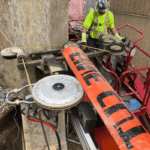
Diamond wire sawing is one common route for slicing hard and brittle materials because a fixed abrasive wire can reduce material loss and support thin-wafer work. Research on diamond wire sawing connects wire wear, cutting force, surface state, and wafer quality, which is why slicing parameters belong in fab-adjacent process planning.
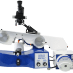
For silicon wafer projects, anchor RFQ discussions around process ranges such as 10-25 m/s wire speed, 60-120 um wire diameter, 0.3-1.0 mm/min feed rate, 20-40 N wire tension, TTV under 10 um, Ra 0.3-0.6 um, 100-180 um semiconductor wafer thickness, and 60-120 um kerf loss. The linked silicon wafer cutting wire saw resource is the commercial handoff for those slicing requirements.
| Slicing Spec | Metric Check | RFQ Use |
|---|---|---|
| Wire speed | 10 m/s equals 600 m/min; 25 m/s equals 1500 m/min. | Ask whether the test cut used the same speed band. |
| Wire diameter | 60 um equals 0.06 mm; 120 um equals 0.12 mm. | Tie wire size to kerf budget and breakage risk. |
| Feed rate | 0.3 mm/min to 1.0 mm/min is a narrow process band. | Record feed rate with material lot and coolant. |
| TTV target | 10 um equals 0.01 mm. | Check whether the measurement plan covers edge and center. |
| Surface roughness | Ra 0.3 um to 0.6 um equals 0.0003 mm to 0.0006 mm. | State whether post-cut polishing is part of the project. |
| Wafer thickness | 100 um to 180 um equals 0.10 mm to 0.18 mm. | Reserve extra trial wafers for handling and fracture checks. |
| Kerf loss | 60 um to 120 um equals 0.06 mm to 0.12 mm. | Use it as a material-cost baseline for the quote. |
| Trial window | A 2 months to 3 months pilot project can expose wire wear drift. | Compare the first batch with the 3 months baseline before scale-up. |
| Wafer-Prep Field | Why a Fab Cares | Sourcing Cue |
|---|---|---|
| Thickness target | Affects handling, polishing allowance, and downstream mechanical risk. | State final and pre-polish thickness separately. |
| TTV | Poor thickness uniformity can raise polishing load and flatness risk. | Ask for measured TTV under your cut recipe. |
| Surface roughness | Sets the burden for later lapping, polishing, and cleaning. | Tie Ra target to the post-cut plan. |
| Kerf loss | Material loss affects cost per wafer and yield per ingot. | Match wire diameter and tension to material value. |
| Wire wear | Changing cutting force can change wafer surface state. | Define replacement rules and inspection intervals. |
The slicing method may vary for compound semiconductor projects. For power electronics and other hard and brittle substrate applications, compare the SiC wafer cutting saw path with the silicon process. The sapphire cutting wire saw page offers a comparable point of reference for LED and optical substrate work.
Yield Risk: Contamination, Flatness, and Process Drift
 7")
Rarely is wafer yield loss attributable to one cause. A fab team might identify a symptom in its probe data, but the problem might actually be residing in cleaning, handling, wafer geometry, film stress, tool drift or a supplier change made weeks ago.
| Risk Level | What to Watch | Control Method |
|---|---|---|
| 1. Incoming material | Wafer thickness, bow, warp, edge chips, particles. | Incoming inspection and supplier certificates. |
| 2. Clean state | Particles, metals, organics, water marks. | Clean recipes, particle monitors, carrier control. |
| 3. Tool drift | Film thickness, etch rate, temperature, pressure, plasma behavior. | Run charts, chamber matching, preventive maintenance. |
| 4. Pattern transfer | Overlay, focus, dose, resist residue. | Inline metrology and feedback loops. |
| 5. Late discovery | Defects found after expensive process time. | Earlier inspection and better sampling at high-risk steps. |
This is why wafer slicing isn’t a secondary issue. If a cut process results in hidden subsurface damage or unstable surface quality, the fab may not know there’s an issue until much later after some cost-adding processing steps in cleaning, polishing, deposition or thermal have already taken place.
Process control starts before the first fab recipe. A supplier change in wire, coolant, feed rate, or handling can shift incoming wafer behavior enough to confuse later metrology trends.
The 8-Variable Fab-to-Wafer Slicing Matrix
 8")
The 8-Variable Fab-to-Wafer Slicing Matrix offers equipment buyers a concrete tool for mapping fab requirements to pre-fab slicing. It can be used prior to issuing an RFQ for a silicon wafer saw, multi-wire saw or lab slicing system.
| Variable | Specify This | Why It Matters |
|---|---|---|
| 1. Material | Silicon, SiC, sapphire, GaN, glass, ceramic, or test coupon. | Hardness and brittleness change wire choice and feed behavior. |
| 2. Diameter or blank size | Lab sample, custom ingot, 150mm, 200mm, 300mm, or non-round blank. | Machine envelope and wire path must fit the part. |
| 3. Thickness target | Final thickness, pre-polish thickness, and tolerance. | Thin wafers raise breakage and handling risk. |
| 4. Kerf budget | Allowed material loss per cut. | Material cost and wafer count per ingot depend on it. |
| 5. TTV limit | Total thickness variation target, measured method, and sample plan. | TTV affects polishing allowance and flatness control. |
| 6. Surface finish | Ra target, saw mark limit, and downstream finishing path. | Rougher cuts can move cost into lapping and polishing. |
| 7. Throughput target | Research, pilot, batch, or production line rate. | Single-wire, endless loop, and multi-wire saw systems serve different volume needs. |
| 8. Handling and inspection | Carrier, cleaning, wafer map, inspection, and traceability plan. | A good cut still fails if handling adds particles or chips. |
| 9. Change control | Wire lot, coolant, tension, feed, and replacement rules. | Stable inputs reduce unexplained process drift later. |
How to turn the matrix into a supplier brief
A useful RFQ does not start with “send a quote for a wire saw.” It starts with the wafer state the fab needs to receive. That means the buyer should share the material family, blank geometry, target thickness, cut face requirement, allowed kerf, inspection method, sample quantity, and follow-on process. A supplier can then talk about wire diameter, wire tension, feed rate, coolant, carrier design, throughput, and test cuts with fewer guesses.
- Start with the wafer or substrate drawing, not only the machine model.
- State whether the cut face will be lapped, polished, etched, cleaned, bonded, or inspected as-cut.
- Separate pilot needs from production needs, because a lab cut and a batch line may need different wire systems.
- Ask for measurement evidence: TTV method, roughness method, inspection area, sample count, and any rejected pieces.
- Define the change-control plan for wire lot, coolant, tension, feed rate, and operator setup.
- Reserve trial material for destructive inspection, since surface marks and subsurface damage may not be clear from a visual check.
Buyers who are still choosing a machine architecture can compare the single-wire saw technology guide with multi-wire options. Teams running lab samples should also review laboratory wire saw maintenance and diamond wire saw safety guidelines before planning test cuts.
For lower-volume research work, compare single-wire saw systems and endless wire saw machines. For brittle-material programs outside silicon, DONGHE’s hard and brittle material cutting hub is a broader entry point.
Where Semiconductor Fabs Are Being Built and Why the Map Matters
 9")
Fab maps are useful, but they can mislead buyers if every marker is treated as the same kind of facility. SIA’s ecosystem map separates fabless, foundry, IDM, OSAT, equipment, materials, and university R&D partners, while OECD separates fabs by status such as planned, under construction, and production.
Are there any semiconductor plants in the US?
Yes. U.S. semiconductor investment includes fabs, packaging sites, materials plants, equipment suppliers, and R&D sites. CHIPS/NIST states that the CHIPS and Science Act gave the Department of Commerce $50B, including $39B for facilities and equipment incentives and $11B for R&D.
| Map Label | What It Means | Supplier Timing |
|---|---|---|
| Planned fab | Publicly announced or in planning. | Early supplier education and spec work. |
| Under construction | Building and utility work are active. | Facilities, tooling, sample flows, qualification plans. |
| Production fab | Wafers are running through qualified processes. | Stable supply, change control, spare parts, process support. |
| OSAT | Assembly and test after wafer fabrication. | Dicing, thinning, handling, package-driven wafer needs. |
| Equipment or materials site | Supplier plant, not necessarily a chip fab. | Tool availability, materials lead time, local support. |
2026 Outlook: AI, HBM, Advanced Packaging, and Wafer Fab Equipment Demand
 10")
Fab planning in 2026 sits at the crossing point of AI compute demand, high-bandwidth memory, advanced packaging, regional policy, and capacity additions. SEMI forecasts semiconductor manufacturing equipment sales of $133B in 2025, $145B in 2026, and $156B in 2027. It also projects wafer fab equipment at $135.2B in 2027.
Those numbers should not push buyers into vague urgency. They should sharpen the sourcing brief. More fab investment means more pressure on clean wafers, qualification data, tool uptime, recipe stability, and supplier response time.
| Signal | What Changes | Buyer Action |
|---|---|---|
| AI and HBM demand | Higher pressure on advanced wafer and packaging flows. | Align wafer thickness, flatness, and handling assumptions early. |
| Regional fab buildout | More suppliers compete for tools, spares, facilities talent, and materials. | Lock process trials and acceptance tests before the ramp. |
| Thinner wafers | Breakage, saw marks, warp, and wire wear become harder to manage. | Test wire, feed, tension, and handling as one process, not as separate purchases. |
| Compound semiconductor growth | Hard brittle substrates need different cutting, cleaning, and inspection plans. | Run material-specific trials for SiC, sapphire, GaN, or ceramics. |
Readers comparing wire saw systems can continue with DONGHE’s high-tech precision cutting hub or review related guides on how a diamond wire saw works, types of multi-wire saw machines, silicon wafer cutting, and SiC wafer multi-wire saw selection.
FAQ
What is a semiconductor fabrication plant?
Short answer
A semiconductor fabrication plant turns prepared wafers into patterned integrated circuits.
What is the difference between a fab and a foundry?
Fab vs. foundry
A fab is the manufacturing plant. A foundry is a business model in which that plant makes chips for outside customers. An IDM may own fabs and make chips for its own product lines.
How long does it take to build a semiconductor fab?
Build timing
The schedule changes with site preparation, permits, cleanroom scope, utility capacity, process node, tool delivery, and customer qualification. Public announcements often describe multi-year buildouts, but suppliers should track the ramp stage more closely than the headline date, because a planned site, a building under construction, a qualification line, a pilot line, and a production fab create very different timing for samples, spare parts, fixtures, training, and acceptance testing.
What equipment is used in a semiconductor fabrication plant?
Equipment groups
Core wafer fab equipment includes lithography, deposition, etch, ion implantation, CMP, clean, wet process, metrology, inspection, automation, and facility support systems. Upstream wafer preparation may add slicing, grinding, polishing, cleaning, and inspection tools.
Why are semiconductor fabs so expensive?
Cost drivers
Costs come from process tools, cleanrooms, utilities, power, water, chemicals, gases, abatement, automation, metrology, safety systems, qualified staff, and long ramp cycles. A fab also needs redundancy, monitoring, trained maintenance teams, qualified suppliers, and strict change control, so the budget covers a manufacturing line and the plant systems that keep that line stable every hour.
Where does wafer slicing happen in chip manufacturing?
Wafer slicing stage
Wafer slicing happens before front-end fab processing. It converts an ingot or blank into wafers that can later be lapped, polished, cleaned, inspected, and sent into the fab. The slicing step affects kerf loss, TTV, surface condition, subsurface damage, and breakage risk.
What does WSPM mean?
Capacity metric
WSPM means wafer starts per month, a fab capacity metric.
Are semiconductor fabs the same as chip packaging plants?
Front end vs. back end
No. A fab handles front-end wafer fabrication. Packaging and assembly happen after wafer fabrication, when die are separated, connected, protected, and tested in package form. Advanced packaging can sit very close to fab strategy, but it is still a different manufacturing stage.
References
- OECD, The Chip Landscape PDF.
- Semiconductor Industry Association, Semiconductor Ecosystem Map.
- CHIPS for America/NIST, CHIPS Program information.
- ISO, ISO 14644-1:2015 cleanroom standard page.
- Circuits Assembly, SEMI equipment sales forecast coverage.
- Materials, through PMC, Experimental study on wire-saw wear and silicon wafer surface.
- Micromachines via PMC, Recent advances in precision diamond wire sawing monocrystalline silicon.