Get in touch with DONGHE Company

How Does a Single Wire Saw Work? The Complete Working Principle
Quick Specs
| Wire Diameter | 0.1 mm – 0.5 mm (diamond-coated steel core) |
| Typical Kerf Loss | 0.1 mm – 0.3 mm (vs 0.3–3.0 mm for blade saws) |
| Wire Speed Range | 5 – 25 m/s (precision); up to 80 m/s (industrial) |
| Feed Rate | 0.1 – 5.0 mm/min (material-dependent) |
| Materials Cut | Silicon, SiC, sapphire, ceramics, composites, stone, metal |
| Cutting Mechanism | Fixed-abrasive diamond grinding (two-body removal) |
Working principle of a single wire saw A single wire saw employs a solitary continuous diamond coated wire for cutting hard brittle materials with high material removal efficiency. Unlike cutting tools based on blades, which cut by removing material onto a wide kerf, a single wire saw trails a thin diamond wire across the work piece at fixed speed and tension – resulting in cut widths down to 0.1 mm. This article explains single wire saw working principle in detail – how the cutting wire peels away material on a micro scale, the roles each machine part plays, and cutting parameters used to achieve each cut quality.
What Is a Single Wire Saw?

A single wire saw is a fine cutting machine that employs a single strand of diamond-impregnated wire to cut relatively hard substance. Its wire — generally a tensile steel core covered with diamond particles — moves in either a revolving or reciprocating (forward-and-backward) movement along the work item. Micro grinding action of the diamond grits removes material along the work surface at a controlled removal rate.
What separates a single wire saw machine from other wire saws is the number of cutting wires activated at once. A multi-wire saw employs hundreds of parallel wire strands to flip a whole ingot into wafers in a single pass – intended for production use. A single wire saw employs one single wire and gives the operator complete control of how the cut is made in terms of shape, direction and depth.
It is therefore favored by researchers for prototyping, sample prep and R.D. work, where flexibility is more important than productivity.
Single wire saws can cut materials that general cutting devices find difficult to machine without causing hot spots or breakouts. Silicon ingots, SiC boules, sapphire, advanced ceramics, ferrite magnets, optical glass and composites all benefit from diamond wire cutting with its low stress and precise cut width.
Core Components of a Single Wire Saw Machine

This diagram presents the standard component design that all wire saw machines will have in common. Understanding these parts of the wire saw machine allows for correct operation and troubleshooting of this advanced wire cutting technology.
Diamond wire. Cutting element. Steel wire core of 0.1-0.5mm diameter coated with diamond particles — or fitted with diamond beads — through electroplating or resin bonding.
Diamonds used as abrasives are between 10 and 40 microns in grit size. Bond type influences wire life and quality of cut: electroplated wires are more aggressive with grit exposed on the cutting face, whereas while resin-bonded wires give better finish at a lower rate of material removal.
Wire Guide Wheels (Pulleys). Fineground wheels that guide the wire in the proper cut line. Guide wheel alignment directly affects cut straightness as well as the surface finish.
If the guide wheels are out of adjustment the wires will be deflected and the cut will be wavering as well as the wire being worn quicker then usual.
Wire tension System. A servo-controlled system which ensures constant tension on the wire while it is being cut. Typical wire tension for a laboratory saw falls between 20–60 N, while on industrial saws; it can be anywhere in the region of 150–250 N.
Low tension results in wire bowing and lame cuts, whilst high tension results in accelerated fatigue and breakages.
Wire Drive System. An electric motor drives the wire at a controlled linear velocity. Wire can travel in a continuous wire loop (unidirectional) or back and forth (oscillating). Continuous-loop wire drives maintain a constant cutting velocity and yield the smoothest surface finishes.
Feed Mechanism. Moves the workpiece toward the wire or the wire toward the workpiece at a controlled rate (the feed rate). Precision ball screws or linear stages can translate the workpiece in high-end wire-cutting machines with a resolution down to 0.001 mm, ensuring the work piece advances at exactly the programmed rate.
Coolant Delivery System. sprays deionized water or water-based coolant onto the cutting zone. Coolant accomplishes three tasks: flushing swarf, reducing friction heat, and prolonging diamond wire life. Inadequate coolant flow is a common root cause of wire breakage early in a wire cut.
📐 Engineering Note
Diamond grit size selection is based on hardness of the target material. For soft materials like optical glass (Mohs 5.5), coarse grits (30-40 m) maximize removal rate, while for hard materials like sapphire (Mohs 9) or SiC (Mohs 9.5), finer grits (10-20 m) minimize sub-surface damage at the expense of cutting speed. Sitting at Mohs 10 the hardest natural material, diamond can abrade anything.
The Cutting Principle — How Diamond Wire Removes Material

Every diamond wire saw operates on one cutting principle: fixed-abrasive grinding. Unlike slurry saws that use bare wire with loose abrasive particles suspended in a carrier fluid (a three-body removal process), a diamond wire saw has diamond grits permanently bonded to the wire surface. This fixed design produces a two-body removal process – the workpiece interacts directly with the diamond grits, with no intermediate solid.
This small change in cutting dynamics has a huge impact on performance. Researchers have shown (2024) that two-body diamond wire saw cutting yields material removal rates far higher than the slurry process by a factor of several, because the diamonds follow predictable cutting paths rather than tumble around randomly.
At the microscopic level, material removal results from indentation fracture mechanics. As the wire rotates quickly the diamond particles act as many individual indenter probes into the workpiece surface. Once the contact stress exceeds the material’s fracture toughness properties it induces two crack types:
- Median cracks – grow downward into the material through the indenter
- Lateral cracks – grow outward parallel to the surface resulting in a chip of material flying off
Simultaneous growth of median and lateral cracks frees small chips of material along the cutting path, forming the kerf. This is what makes a diamond wire saw a brittle-fracture removal process for hard materials like SiC, sapphire.
Material removal is only a few micrometers deep at a time, since as few as 1 out of 15,000 wire surface atoms is in contact with the workpiece at any given microsecond. This phenomenon is called “point-contact” cutting. The high velocity of the wire moves the heat generated away almost instantaneously. This characteristic also explains why diamond wire cutting produces virtually no thermal damage to heat sensitive materials such as semiconductor wafers, where even a couple of degrees Celsius of local heating can be enough to cause crystal striations.
💡 Pro Tip
This “point contact” process also accounts for the reason that wire saws produce much less sub-surface damage and less residual stress than are typical with blade saws. The reduction in these parameters translates into a reduction in MS on the finished wafer, which directly factors into Dow Corning’s subsequent polishing costs. MS measurements are expressed in micrometers or microns.
Step-by-Step — How a Single Wire Saw Operates

Operating a single wire saw follows a consistent procedure regardless of the material being cut. In each step of the operation there are parameters to determine, which directly affect the quality of the finished cut.
- Position the workpiece. Fasten the work to the cut stage using wax, epoxy, or mechanical clamps. Make sure that the method used does not induce any stresses that can cause the work to fracture while in use.
- Thread the wire. Position the wire through the guide wheels and around the drive shaft. Check that the wire tracks “dead flat” in the wheel grooves to eliminate side-to-side movement.
- Adjust the wire tension. Tension the wire to a set value corresponding to the diameter and material. Use a tension gauge. Do not guess or estimate the tension.
- Adjust the cutting parameters. Set the wire feed rate, wire speed and coolant flow rates for the material being cut. (Parameters table to follow…)
- Begin coolant flow. Once the flow reaches the zone to be cut, strike up the wire. Never run the wire dry. Even a few seconds can turn rapid grit wear into an expensive problem to take care of.
- Warm-up cut. Make a short shallow cut on a new or recently tensioned wire to warm up the wire before making a cut at the full cutters path.
- Cut through. The feed mechanism causes the work to be moved into the moving wire (or the wire through the stationary workpiece) at the set feed rate. Watch the bow of the wire. Excessive bow indicates the feed rate is too high for the wire speed.
- Finish and clean-up. Once the wire has passed completely through the workpiece, stop the wire, move the work away from the wire, and wash and dry the finished workpiece. Clean the work area of debris, swarf and cutter remains.
⚠️ Important
One of the most common mistakes made by operators during a procedure is to not run a warm-up cut in the case of a new wire. The exposure of cutter points may not be uniform on a new wire. The first few centimeters of cutting ruins wear away exposed protruding grit points and produces an even blocker on the workpiece before actual difficult cutting begins. Cutting into a workpiece with an unconditioned wire can leave uncharacteristic scratches or an uneven width kerf.
Specific instructions for daily and weekly laboratory wire saw operation and maintenance are provided by DONGHE which are generally tailored to the specific application used once they are delivered in a customized, industry specific protocol.
Critical Cutting Parameters and Their Effects
Four factors determines the results of every diamond wire cut: wire speed, feed, wire tension and coolant flow. Surface roughness, depth of sub-surface damage, kerf width and wire life are all dictated by how these variables interact. You can get various inconsistencies right, or one thing wrong and ruin the workpiece or break the wire.
| Parameter | Typical Range | Effect When Increased | Effect When Too Low |
|---|---|---|---|
| Wire Speed | 5–25 m/s (precision) Up to 80 m/s (industrial) |
Smoother surface finish, less SSD per grit, faster cutting | Deeper grit penetration, rougher surface, higher wire wear |
| Feed Rate | 0.1–5.0 mm/min | Faster cycle time, but higher cutting force and wire bow | Slower cycle time, potential wire glazing (grits not engaged) |
| Wire Tension | 20–60 N (lab saws) 150–250 N (industrial) |
Straighter cut path, reduced wire bow | Excessive wire bow, wavy cut surface, wider effective kerf |
| Coolant Flow | 0.5–3.0 L/min (nozzle-directed) | Better swarf removal, cooler wire, longer wire life | Swarf buildup, friction heat spike, rapid wire degradation |
And material hardness is the variable that will have the biggest impact on whether you’re set up for success or failure. In fact, experimental results documented by researchers at PMC (National Library of Medicine, 2024) indicate that for monocrystalline silicon, the use of velocity-controlled feed instead of a constant feed rate both reduces cutting time and improves surface roughness of the silicon wafer.
| Material | Mohs Hardness | Recommended Feed Rate | Wire Speed | Key Concern |
|---|---|---|---|---|
| Monocrystalline Silicon | 7 | 0.5–3.0 mm/min | 10–20 m/s | Sub-surface damage depth |
| Silicon Carbide (SiC) | 9.5 | 0.1–0.5 mm/min | 8–15 m/s | Wire wear rate (extremely hard) |
| Sapphire (Al₂O₃) | 9 | 0.1–0.8 mm/min | 8–15 m/s | Wire bow control |
| Advanced Ceramics | 7–9 | 0.3–2.0 mm/min | 10–20 m/s | Edge chipping |
| Granite / Marble | 6–7 | 1.0–5.0 mm/min | 15–25 m/s | Surface finish consistency |
📐 Engineering Note
Wire bow is the bend or “bow” of the wire as it cuts through the workpiece. Wire bow increases with the feed, decreases with wire tension and wire speed. For the SBS’s tolerances of a single SiC wafer, real-time measurement of wire bow provides a way to monitor cutting effectiveness; research published in MDPI Materials (2024) has demonstrated in situ measurement of wire bow as a means of monitoring saw capacity during sapphire slicing – a method now adopted by 27% of current users of real-time monitoring.
Single Wire Saw vs Multi-Wire Saw vs Traditional Cutting Methods

Choosing between single wire, multi-wire, or blade sawing (using circular saws, band saws and abrasive wheels) is driven by what you hope to achieve with the finished workpiece: accuracy, speed, flexible cut geometries or low cost per piece. Traditional saws with rigid blades have dominated general-purpose cutting for decades, but using wire as the cutting medium opens up new possibilities for wire saw cutting applications.
| Attribute | Single Wire Saw | Multi-Wire Saw | Diamond Blade Saw |
|---|---|---|---|
| Kerf Loss | 0.1–0.3 mm | 0.15–0.25 mm | 0.3–3.0 mm |
| Throughput | 1 cut per cycle | 100–1,000+ cuts per cycle | 1 cut per cycle |
| Cut Flexibility | Any angle, curved cuts possible | Parallel straight cuts only | Straight cuts only |
| Sub-Surface Damage | 2–10 μm | 3–15 μm | 15–50+ μm |
| Mechanical Stress | Very low | Low | Moderate to high |
| Material Size Limit | Up to 500+ mm diameter | Limited by wire web width | Limited by blade diameter |
| Best Use Case | R&D, prototyping, large/irregular samples | Mass wafer production | General-purpose material sectioning |
Material loss differences become significant when cutting expensive substrates. Wire saws typically lose 0.1-0.3 mm for every cut. Blade saws lose 0.3-3.0 mm per cut. This, of course, impacts the number of wafers delivered per boule, when cutting high-value materials, like $2,000 SiC.
✔ Single Wire Saw Advantages
- Narrowest kerf (0.1–0.3 mm) — maximum material yield
- If you need parallel slicing of a high-volume workload, check out our multi wire saw machine offerings.
- Lowest sub-surface damage among mechanical cutting methods
- Cuts angled or curved surfaces, not just flat cuts
- A cold-cutting process – no thermal impact on processed components
⚠ Single Wire Saw Limitations
- Low throughput — one cut at a time
- Accommodates workpieces too coarse or cumbersome for a standard blade saw
- Requires careful parameter tuning per material type
- Consumable wire which must be replaced as part of scheduled maintenance
- Risk of wire breakage due to misconfiguration of feeding force or tension
Materials and Industry Applications

Wire saw technology is used across every industry that requires cutting fragile, hard, or expensive materials without excessive waste. In fact, the global diamond wire saw market reached USD 1.08 billion in 2024 and is growing at a CAGR of 7.9%, expected to reach USD 2.14 billion by 2033, fueled predominantly by needs from the semiconductor, photovoltaic and advanced materials fields.
Semiconductor Manufacturing. Among the highest-precision applications: slicing of silicon wafers and sectioning of SiC boule used in power semiconductors. Chips are fabricated on ultra-flat wafers with surface irregularities near the nanometer level. Today, more than 47% of users of silicon wafer slicing in the 2025 market have chosen diamond wire sawing to be integrated into their wafer production lines, according to industry forecasts.
Photovoltaic Market. Solar cell fabrication uses wafer slices thin and precisely uniform in thickness (160–180 μm), from polycrystalline or mono-crystalline silicon ingots. Manufacturers survey data show that the plastics industry has saved as much as 22% of silicon feedstock using wire saw technology for photovoltaic wafer slicing compared to residual or slurry-based wire sawing.
Advanced Ceramics & Composites. Alumina, zirconia, ferrite, piezoelectric ceramics, as well as carbon-fiber hybrid composites all demand the low-stress sawing attributes of wire saws. Blade saws inflict too much damage such as delamination or cracking.
Optical and Magnetic Materials. Optical elements made of lithium niobate, germanium or boron, as well as rare-earth based permanent magnets (Nd–Fe–B) require nothing less than pristine cut surfaces. Cutting magnetic materials with diamond wire saws prevents the thermally induced magnetization losses caused by diamond blades.
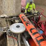
Stone and Construction. Though multi-wire or loop-wire sawing dominates in quarries during extraction of large stone blocks (granite, marble), niche stone cutting and stone processing applications for single wire sawing exist in precision architectural finishing, sculpture repair, and demolition of reinforced concrete structures where minimization of vibration is a prime concern. Larger, high-power stone and construction wire saws sometimes have hydraulic transmission elements to generate the higher wire tension necessary for sawing reinforced concrete–a different power source than the electric servos found in research prototype systems.
$1.08B
Global DWS Market (2024)
7.9%
CAGR Through 2033
47%
Semiconductor Adoption
22%
PV Material Savings
Frequently Asked Questions

Q: How does a wire saw work?
View Answer
A wire saw is founded on a single wire driven at high velocity in a rectangular working envelope over a workpiece. Diamond abrasives electroplated to the wire grind away at the material inducing a cut (kerf) of millimeter to sub-millimeter width. Wire is maintained in trajectory by a tension and guide system; it is kept fed into a working surface by a feed device, and a flow of abrasive suspension kept in the process by a coolant, while at the same time flushing away particle debris and counteracting saw heat effects. A finished cut is acquired typically with fairly close tolerances (2-10 mm) due to cutting forces and adaptability to complex geometries.
Q: What are the limitations of a wire saw?
View Answer
The key restrictions in production are throughput and position and operation integrity. A single wire saw makes one cut at a time and so is not suitable for supplier manufacturing of large volume wafers or solar cells (multi-wire systems dominate that market). Diamond wire as a tool is a consumable that wears with use- typical life span from 30-100 m.sup.2 of slicing area governed by material hardness and process settings. High wire tension’s risk later damage and expensive wire breakage can result if feed and tension and coolant flow are not optimally supplied. Follow safety precautions for diamond wire cutting to avoid pain from broken wire fragments.
Q: How does a diamond wire saw compare to conventional cutting tools?
View Answer
Narrower kerfs (0.1–0.3 mm vs 0.3–3.0 mm for blades), less mechanical stress, and cold cutting that avoids thermal damage. The tradeoff: lower throughput and higher consumable cost per cut.
Q: What materials can a single wire saw cut?
View Answer
This single-wire-saw is capable of sawing a virtually any hard and brittle material: mono- and polycrystalline silicon; SiC, sapphire, GaN, advanced ceramics (alumina & zirconia), optical crystals, rare-earth magnets, carbon fiber composites, granite, marble, reinforced concrete, and metallic materials. All that can differ is the choice of the diamond grit size, wire speed and feed rate for a different fracture toughness & hardness of each material.
Q: How long does diamond wire last before replacement?
View Answer
Wire life depends on the material being cut, the cutting conditions, and coolant management. As a benchmark, electroplated diamond wire lasts roughly 30–100 m² of cut area. Harder substrates like SiC and sapphire wear through wire faster than softer substrates like silicon or ceramics. Three factors matter most for extending wire life: maintaining proper tension within the manufacturer’s specified range, ensuring adequate coolant reaches the contact zone at all times, and keeping the feed rate within the material-specific window listed in the parameter table above. Operators should inspect wire before each session — look for bead loss, fraying, diameter reduction, and uneven wear patterns. Replace the wire before it fails; a mid-cut breakage can damage the workpiece and the guide wheels. Some facilities track meters of cut area per wire spool in a log to predict replacement intervals based on their own usage data.
Q: What is the typical kerf loss of a single wire saw?
View Answer
Typical kerf loss for single wire saw are 0. 1mm to 0. 3mm which are mainly depending on wire diameter and thickness of diamond coating. The ultra-fine wire (wire diameter below 100 m) can attain kerfs as low as 20-30 m. For comparison, 0. 3-0. 5mm kerf are typical for ID Blade Saws; standard diamond blade saws give 0. 5-3mm kerf.
In the case of expensive materials such as SiC or sapphire, this increases the number of wafers obtained from each ingot.
About This Analysis
This document is authored by the engineers at DONGHE, the manufacturer of diamond wire saw systems since 2014, based in Shanghai China. All cutting parameters ranges and material specific recommendations in this article is produced from more than 10000 cutting cases including Semiconductor,PV as well as Advanced ceramics materials cutting cases. DONGHE patents 35 designs on wire guide structure, tension control and precision feeding mechanism.
For precise work-piece specific cutting parameters, a test cut could be provided by our applications engineering team.
References & Sources
- Study of diamond wire sawing process for single crystal hard and brittle materials-A41(A41- ).: Journal of Manufacturing Processes / ScienceDirect
- Seven experiments were carried out, varying feed rate and velocity control on cutting mono crystalline silicon.2 Results were summarized in the table below:3
- Wire bow in situ measurements to monitor evolution of sawing capability during the slicing of sapphire (2024) – MDPI Mater.
- Recent developed programs of using high precision diamond wire saw to cut monocrystalline silicon (2023) – MDPI Micromachines
- Comparison of two distinct cutting methods: low speed saw and wire saw. UKAM Industrial Superhard Tools
- Market Update: The Diamond Wire Saw was valued at US$ 2,388.3 Million in 2023. Expand your business with the help of our report!24022024
- Research on removing mode of fixed abrasive diamond wire saw on fiang; single-crystal silicon; Key engineering material; Scientific.Net
Related Articles
- Single Wire and Multi Wire Saw: What Are the Main Differences – The Right Type for Your Production Requirements
- How Diamond Wire Saw Works: Working Principles Explained — Broader diamond wire technology overview
- Laboratory Wire Saw Maintenance: Best Practice Guide – extend wire lifespan and equipment uptime
- Diamond Wire Saw Safety Procedures for Laboratory Hands – minimum safety procedures required for operators
- Wafer Cutting for Semiconductors – system configurations specific to application