
Get in touch with DONGHE Company


Updated June 2026 · Reviewed by the Shanghai Donghe Science and Technology technical team
A silicon carbide heating element is a non-metallic ceramic resistor, made mostly of recrystallized silicon carbide (SiC), that turns electric current into radiant heat at temperatures far beyond what metal wire can survive. If you run a kiln, a heat-treating furnace, a glass tank, or a high-temperature lab furnace, the SiC element is often the workhorse behind the hot zone. This guide cover what these elements are, how they generate heat, the shapes and specifications you’ll choose between, why their resistance behaves so strangely as they age, how to wire and size them, and where demand is heading.
A silicon carbide heating element is a recrystallized-SiC ceramic rod or tube that converts electric current into radiant heat at element temperatures up to about 1625°C (2957°F). Unlike metal elements, its electrical resistance rise permanently with age, which drives almost every design and wiring rule below.
Quick Specs: Silicon Carbide Heating Elements
| Material | Recrystallized / reaction-bonded alpha silicon carbide (SiC) |
| Max element (surface) temp | Up to ~1625°C (2957°F); ~1550°C for long life |
| Typical furnace range | 600–1600°C, air or many controlled atmospheres |
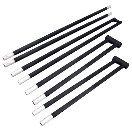
| Forms | Rod, tube, single/double spiral, U, dumbbell, three-phase |
| Diameters / lengths | 0.5–3 in (10–55 mm) / 1–10 ft (to ~6 m) |
| Resistance behavior | Rises with age (drives parallel wiring + matched-set replacement) |
| End-of-life marker | Resistance reaches ~3× the original value |
💡 Key Takeaways
- SiC element resistance climbs irreversibly as it ages, the opposite of how most people expect a heater to behave.
- Lower surface watt loading (W/cm²) is the single biggest lever on service life.
- Wire elements in parallel and replace them as a matched set; never drop one new element into an aged bank.
- SiC owns roughly 600–1600°C; above that, molybdenum disilicide takes over.
What Is a Silicon Carbide Heating Element?
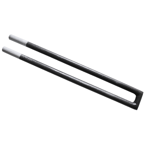
A silicon carbide heating element is a non-metallic, high-temperature ceramic resistor made mostly from recrystallized silicon carbide (SiC), formed and then recrystallized into a dense rod or tube. It converts electric current into radiant heat at element temperatures up to about 1625°C, far beyond what metal wire survives, which is why these elements drive kilns, glass tanks, and heat-treating furnaces.
Silicon carbide itself, also called carborundum, is a compound of silicon and carbon with a hardness above 9 on the Mohs scale, approaching that of diamond, so it survives where metal heaters melt or sag. Most elements use recrystallized SiC, while spiral hot zones are often made from reaction-bonded silicon carbide for extra density.
Two construction families dominate. Recrystallized SiC gives the classic rod with a central hot zone and two cooler ends. Reaction-bonded SiC, used in slotted spiral elements, packs higher density for a smaller cross-section. The same hard, brittle SiC family appears across high-tech precision work, from silicon carbide abrasive grains to the ingots a diamond wire saw slices. According to the U.S. National Institute of Standards and Technology, a recrystallized SiC (Globar) rod was rugged and oxidation-resistant enough to serve as a secondary infrared emission standard, a useful hint at how stable the material is at red heat. For the chemistry and crystal background, see the overview of silicon carbide from Wikipedia.
One practical consequence of that hardness: SiC elements are brittle and crack easily if knocked or clamped carelessly, a trait anyone who has cut SiC ingots learns quickly. In practice, a cracked element is the most common warranty problem on a new furnace, which is why precision-ground cold ends and a tight diameter tolerance of about ±0.5 mm matter at install. As a ceramic material, SiC offers relatively high electrical conductivity for a ceramic, plus strong oxidation and corrosion resistance, low deformation, and the durability that make it one of the toughest heating-element ceramics in service. The best-known brand, Kanthal’s Globar line, helped make recrystallized SiC the default for high-temperature electric furnaces.
How Silicon Carbide Heating Elements Generate Heat

SiC elements heat by Joule heating: a current passes through the element, meets its electrical resistance, and that power become heat, following W = I²R, where W is power in watts, I is current, and R is resistance. The element is shaped so its central hot zone runs at high resistance and glows, while the two cooler ends carry low resistance and stay cool where they cross the furnace wall.
Engineers aluminize those cold ends, and one patented approach enlarges the cold-end cross-section specifically to lower end resistance and keep that heat inside the chamber. Get that hot-zone-to-cold-end ratio wrong and the ends overheat, a failure that cracks the element where it leaves the wall. Engineers size the ratio because the root cause of most early failures is an over-hot cold end, not the hot zone; a production furnace running 24 hours a day at 1400°C punishes any mismatch.
How does a silicon carbide heating element generate heat?
A silicon carbide heating element generates heat resistively: electric current flows through its high-resistance SiC hot zone, and the material dissipates that electrical energy as radiant heat. The hot-zone resistivity is large, roughly 600 to 1400 ohm-mm²/m once its surface reaches about 1050°C, so even a modest current produces intense, uniform radiant heat.
Resistance isn’t constant: from room temperature up to about 800°C it falls (a negative coefficient), then above 800°C it rises again with temperature (a positive coefficient), reaching a minimum somewhere in between. This U-shaped curve is the first quirk a furnace control system has to tame.
When silicon carbide is heated in air it also slowly oxidizes, a reaction that become the central story of element life, explained below. Oxide growth here has been studied at the surface-science level, for example in U.S. Department of Energy work on the oxidation of silicon carbide.
Types and Shapes: Rod, Spiral, Dumbbell, and U Elements
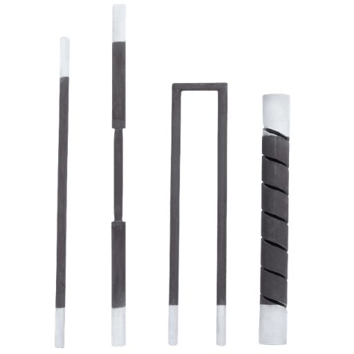
Element shape is chosen to fit the furnace geometry, the wiring layout, and how much hot-zone surface you need. Six families cover almost every furnace:
| Type | Form | Best for |
|---|---|---|
| ED (rod) | Straight rod, hot zone + 2 cold ends | General box and tube furnaces |
| SC (single spiral) | Spiral-slotted hot zone | Higher resistance in a shorter length |
| SG (single spiral, reaction-bonded) | High-density spiral hot zone | Reducing or corrosive atmospheres |
| SCR (double spiral) | Both terminals at one end | Single-end wiring, tight chambers |
| SGR (double spiral, reaction-bonded) | High-density, single-end terminals | Compact high-duty chambers |
| U type | Two legs joined into a hairpin | Both connections on one side |
| DB (dumbbell) | Enlarged cold ends | Lower end losses, less furnace-wall heating |
| Slot (Ux) | Spiral-grooved heating section | Rigorous, corrosion-prone duty |
| LD | Long cold-end rod | Thick furnace walls, deep terminals |
| W (three-phase) | Multi-leg | Three-phase furnace banks |
Choosing the wrong shape is an expensive mistake: a rod that’s too long leaves part of its hot zone inside the furnace wall, where it overheats and cracks. In practice, aerospace and automotive heat-treat shops favor dumbbell ends with enlarged 30 mm cold sections to cut wall losses. Common sizes run 0.5 to 3 inches (10 to 55 mm) in diameter and 1 to 10 feet long, with hot zones up to roughly 4.2 m. Suppliers will customize the configuration, diameter, and length, including helical-slot Type U hairpins, to match your furnace. Note that the spiral slot in a single-spiral element isn’t decorative: it reduces the cross-sectional area of the hot zone, which raises its resistance and keep the ends cool relative to the center, an approach formalized in early silicon carbide element patents.
Temperature Range and Key Specifications
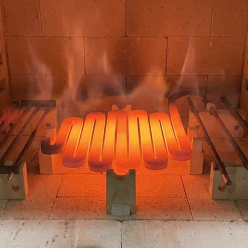
Is silicon carbide heat resistant? Very. SiC heating elements operate at element surface temperatures up to about 1625°C (2957°F), with most furnaces running a continuous 600 to 1600°C. But the headline number is a ceiling, not a cruising speed: run an element continuously near 1600°C and you’ll trade away service life fast, so many designers treat roughly 1550°C, not the headline maximum operating temperature, as the practical long-life ceiling for a high-quality element. SiC keeps useful strength and oxidation resistance at red heat, which is why studies of SiC for high-temperature service at Purdue University highlight its strength retention and high thermal conductivity.
| Property | Typical value |
|---|---|
| Max surface temperature | ~1625°C (2957°F) |
| Specific gravity | 2.6–2.8 g/cm³ |
| Porosity | <30% |
| Bend strength | >300 kg; rupture ~50 MPa at 25°C |
| Thermal conductivity (1000°C) | 14–19 W/m·°C |
| Radiancy (emissivity) | 0.85 |
Values compiled from published SiC element data; confirm against your supplier’s datasheet for a specific grade.
📐 Engineering Note
Separate two numbers that get confused: the element surface temperature and the furnace (chamber) temperature. An element always run hotter than the chamber because heat flows from element to load. A 1600°C chamber can push element surface temperature well above that, which is why the surface-load tables below cap watt density as chamber temperature climbs.
Where Silicon Carbide Heating Elements Are Used
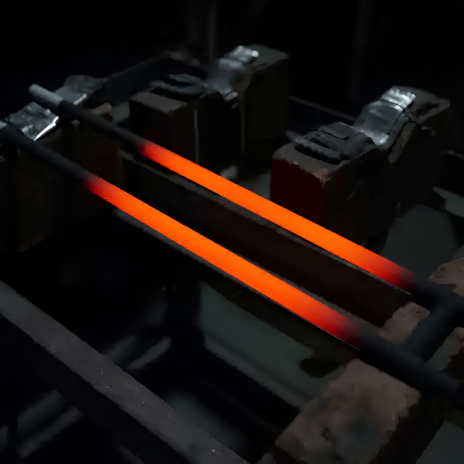
SiC elements are used wherever a process need clean, electric, high-temperature heat in air or a controlled atmosphere: ceramic firing, glass melting and forming, metal heat treating, metallurgy and assaying, powder metallurgy, magnetic-material sintering, waste incineration, and automotive component heat treating. They also anchor laboratory and pilot furnaces.
A risk run through every application: run the element too hot to save on element count and you trade months of service life for a few watts. A medical-ceramics kiln holding 1500°C, for example, will crack elements fast if surface loading isn’t derated. The U.S. Department of Energy notes that industrial process heat is the single largest slice of industrial energy use, so the elements behind those furnaces matter at plant scale.
Semiconductors are a fast-growing home for SiC elements, because the same high-temperature diffusion, oxidation, and sintering steps that make power chips run in exactly the 1200 to 1600°C band SiC owns. That ties the element directly to the broader push to slice harder feedstock: makers of SiC wafer cutting equipment and hard and brittle material cutting lines feed the same supply chain. Brittle non-metal workpieces from advanced ceramics diamond wire saw work to optical blanks rely on the same furnaces these elements heat.
SiC vs MoSi2 vs Metallic Elements: The 1625°C Crossover Window
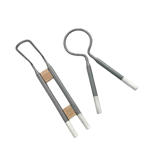
What disadvantages does silicon carbide have? Mostly two: its resistance ages, and its ceiling, while high, isn’t the highest available. That’s where the choice between element families comes in. We call the decision the 1625°C Crossover Window: pick the element whose sweet spot brackets your real operating temperature and atmosphere, not the one with the biggest headline number.
| Element | Practical max | Resistance with age | Pick it when |
|---|---|---|---|
| FeCrAl / NiCr wire | ~1200–1400°C | Rises slowly (NiCr) / stable | Lower-temp, lowest cost |
| Silicon carbide (SiC) | ~1600–1625°C | Rises ~3× over life | 600–1600°C, cycling, cost-sensitive |
| Molybdenum disilicide (MoSi2) | ~1800–1900°C | Stays stable | Above ~1600°C, oxidizing |
Temperature bands are typical; verify against grade datasheets.
Here’s the counter-intuitive part. Molybdenum disilicide goes hotter than SiC and, critically, its resistance barely change over its life, so it doesn’t force the voltage chase that aging SiC demands. So why not always use MoSi2? Because it has its own trap: MoSi2 suffers from accelerated pest oxidation in the 400 to 600°C range that can crumble the material, and it’s more fragile when hot. Unlike tungsten elements, which demand vacuum or inert gas, SiC runs in plain air; it’s also cheaper than MoSi2, tolerates thermal shock better (it can ramp roughly 12 to 18°C per minute), and is happy cycling on and off. The honest summary: SiC isn’t the best high-temperature element, it’s the best in its window.
✔ SiC Advantages
- Lower cost than MoSi2
- Strong thermal-shock tolerance
- Good for on/off cycling
- Wide atmosphere compatibility
⚠ SiC Limitations
- Resistance rises with age (voltage chase)
- Ceiling below MoSi2
- Hard and brittle, cracks if mishandled
- Moisture-sensitive in storage
Element Life: The Resistance-Climb Clock and the Surface-Loading Life Budget
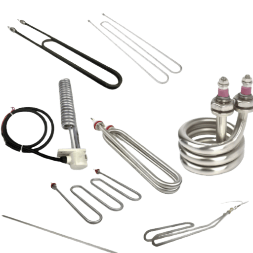
Why does a silicon carbide heating element’s resistance increase over time? Because it slowly oxidizes. In air, the SiC surface begins to oxidize around 800°C, forming a protective silica (SiO2) film between roughly 1000 and 1300°C. That film actually helps: it passivates the surface and slows further oxidation, stabilizing near 1500°C. Its trade-off is that the oxide keep thickening over thousands of hours, and that growth steadily raises the element’s electrical resistance. We call this predictable drift the Resistance-Climb Clock: a SiC element doesn’t fail suddenly, it ages on a schedule you can read from its rising resistance.
This silica passivation follows the classic parabolic, self-limiting oxidation described in a peer-reviewed review of silicon carbide oxidation behavior, and the underlying thermal-oxidation physics is detailed in work on thermal oxidation of SiC at TU Wien. A practical rule of thumb in the field, call it the 3x Resistance Rule, is that an element is finished when its resistance reach about three times its original value. There’s also a cliff: push the surface above roughly 1627°C and the protective film breaks down, oxidation accelerates, and the element fails early, which is exactly why running at the rated ceiling is a mistake. Careful manufacturing process control applies a protective coating, and high-density (HD) grades resist corrosive atmospheres better, both of which cut downtime by stretching the interval between element changes. Because the root cause is oxidation, the structural fix is lower loading and a protective coating, not a hotter element; certified high-density grades hold tolerance on resistance longer. Because aged elements can usually be swapped while the furnace is hot, planned replacement avoids leaning on backup heat sources.
“We watch the amperage. As long as current draw holds steady after the furnace reaches temperature, the elements aren’t aging fast. A slow climb in the voltage we need to hit setpoint is the real fuel gauge.”
Your single biggest lever is surface watt loading, the power dissipated per unit of radiating surface (W/cm²). Think of it as a Surface-Loading Life Budget: every furnace temperature sets a ceiling on watt density, and spending under that ceiling buy run-time. As one furnace builder put it, SiC elements “last longest if you keep their surface loading low.”
| Furnace temp (°C) | Max surface load (W/cm²) |
|---|---|
| 1100 | <17 |
| 1200 | <13 |
| 1300 | <9 |
| 1350 | <7 |
| 1400 | <5 |
| 1450 | <4 |
💡 Worked Example: Spending the Life Budget
Take a 1400°C furnace, where the ceiling is about 5 W/cm². A 25 mm (1 in) diameter rod with a 500 mm (20 in) hot zone has a radiating surface of roughly π × 2.5 cm × 50 cm ≈ 393 cm². At the 5 W/cm² ceiling that element can carry up to 393 × 5 ≈ 1,965 W. Design instead at half the ceiling, about 2.5 W/cm² (≈ 980 W per element), and you add elements rather than push each one harder, which stretches run-time before the Resistance-Climb Clock forces replacement. Plug in your own diameter, hot-zone length, and furnace temperature and the same arithmetic sizes your bank.
Wiring and Installation Best Practices
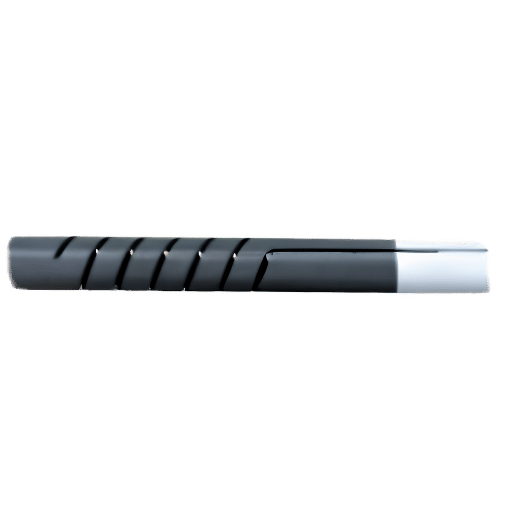
Because resistance drifts upward as elements age, wiring isn’t a footnote, it’s a direct consequence of the Resistance-Climb Clock. Elements connected in series or parallel won’t share power equally unless their resistances match, so a mismatched element get over-powered and burns out early. Two rules follow directly.
- ✔Prefer parallel connections. If you must use series, keep no more than about three branches in series.
- ✔Match element resistance within roughly ±5 to ±10% across a bank, and replace the bank as a matched set.
- ✔Use a multi-tap transformer or an SCR (silicon-controlled rectifier) controller, and raise voltage slowly at start-up to avoid a current surge that cracks cold elements.
- ✔Clamp the aluminized cold ends firmly with M, C, or G clamps and aluminum braid; a loose joint arcs and destroys the end. The enlarged low-resistance cold end that makes this connection reliable is itself a patented element design.
- ✔Drill the wall passage about 1.5× the cold-end diameter, pack lightly with ceramic fiber, and keep stored elements dry.
⚠️ The Most Expensive Mistake
Dropping a single new, low-resistance element into a bank of aged, high-resistance ones. That new element draws a disproportionate share of the power, overheats, and fails within weeks. When one element in an old bank dies, either match the replacement to the current (aged) resistance of its neighbors, or replace the whole set. For ultimate protection, give each element its own controller.
On a production line running 24 hours, a single mismatched element can fail in weeks; matching resistance within 10% and torquing clamps to spec is the difference between a year of service and a month. Element installation and resistance behavior also intersect safety standards for electroheat installations such as IEC 60519, which governs the broader furnace system the elements sit inside.
How to Select and Size Silicon Carbide Elements
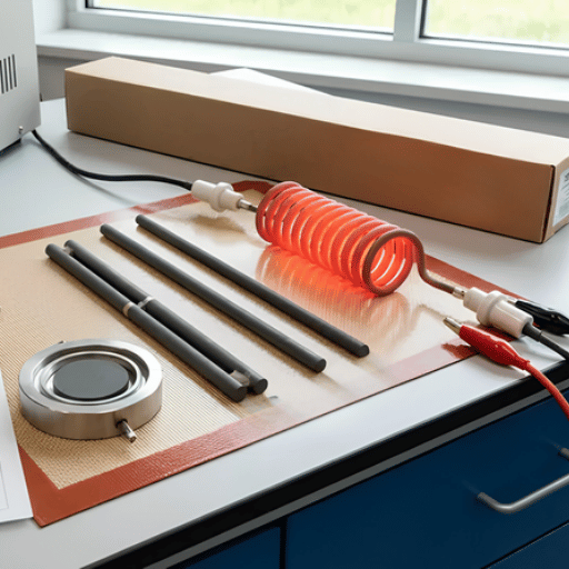
Turning all of the above into a purchase order come down to a short, repeatable checklist. Work through these six steps in order, covering operating temperature, surface-load cap, hot-zone length, atmosphere, voltage headroom, and element form, and you’ll hand a supplier a complete specification they can quote against without guesswork or costly back-and-forth.
The 6-Step Element Sizing Checklist
- Operating temperature: set both the furnace temperature and the element surface temperature; stay roughly 75°C below the rated ceiling, because SiC keeps its strength at elevated temperature only below that line.
- Surface-load cap: read the W/cm² ceiling for that temperature, then design at half of it.
- Hot-zone length: match the heated section to the chamber so cold ends sit in the wall, not the hot zone.
- Atmosphere: choose a coating (A, B, or alkali-resistant) for reducing, nitrogen, or alkali-laden environments.
- Voltage headroom: size the transformer or SCR so you can raise voltage as elements age and resistance climbs.
- Form and wiring: pick rod, spiral, U, or dumbbell to fit the chamber and your parallel layout, and order matched resistances.
Exact dimensions depend on your furnace, so request a resistance-matched set built to your hot-zone and cold-end lengths rather than ordering generic stock.
Atmosphere is the step engineers most often get wrong, because the same element tolerates very different temperatures and watt loadings depending on the gas around it. Use this reference to set the cap before you size power:
| Atmosphere | Max furnace temp (°C) | Surface load (W/cm²) |
|---|---|---|
| Air (clean oxidizing) | 1600 | per temperature table |
| 18% CO | 1500 | 4.0 |
| CO2 | 1450 | 3.1 |
| Nitrogen | 1370 | 3.1 |
| Methane | 1370 | 3.1 |
| Hydrogen | 1290 | 3.1 |
| Ammonia | 1290 | 3.1 |
| Vacuum | 1204 | 3.8 |
| Water vapor | 1090-1370 | 3.1-3.6 |
| Halogen | 704 | 3.8 |
Reducing and carbon-bearing atmospheres attack the protective silica film, which is why they cap temperature and loading; a quartz tube or protective coating can recover some headroom. In nitrogen, hold the surface load near 3.1 W/cm²; in 18% CO you can push to about 4 W/cm², but in a halogen atmosphere keep the furnace below 704°C and protect the element.
Industry Outlook: Where SiC Heating Element Demand Is Heading
The load-bearing driver for SiC heating elements isn’t a market chart, it’s a build-out. Power-semiconductor fabs for electric vehicles and grid electronics are multiplying, and the steps that turn raw silicon wafer material and SiC boules into working silicon carbide MOSFET devices run high-temperature diffusion, oxidation, and sintering in exactly the 1200 to 1600°C band these elements own. Every new fab line is a derivative pull on SiC furnace elements.
Policy is the second driver. The U.S. Department of Energy’s Industrial Heat Shot targets cost-competitive industrial heat with at least 85% lower emissions by 2035, which favors electrified resistance heating powered by clean electricity over fuel-fired furnaces. That structural shift toward electric process heat is tailwind for every clean high-temperature element. Market researchers project the SiC electric heating element market growing in the high single digits annually through the mid-2030s, but treat those figures as directional background; the real signal for a buyer planning a 2026 furnace project is that electric high-temperature capacity is being added, not retired. For buyers planning a 2026 line, the trap is specifying elements at today’s temperature, then discovering the process crept to 1500°C; retrofitting hotter elements mid-production is expensive, and power-device fabs running 1300°C diffusion furnaces face exactly this. If you’re specifying a new line, design the element bank for the upper end of your temperature range now, because retrofitting hotter elements later is far costlier than buying headroom today.
Frequently Asked Questions
Q: What is a silicon carbide heating element?
View Answer
A silicon carbide heating element is a non-metallic, high-temperature heating element made mainly from recrystallized silicon carbide. Current passing through its high-resistance hot zone produces radiant heat by Joule heating, reaching element surface temperatures up to about 1625°C. Because it’s a hard, oxidation-resistant ceramic rather than a metal wire, it works in furnaces far hotter than nickel-chrome or iron-chrome-aluminum elements can survive, which is why it’s standard in kilns, glass tanks, and heat-treating furnaces.
Q: What temperature can a silicon carbide heating element reach?
View Answer
Element surface temperatures reach roughly 1625°C (2957°F), with most furnaces running a continuous 600 to 1600°C. That ceiling is a maximum, not a target: running near 1600°C accelerates oxidation, so many engineers treat about 1550°C as the practical long-life limit.
Q: Why does a SiC heating element’s resistance increase over time?
View Answer
In air, the silicon carbide surface slowly oxidizes and grows a silica (SiO2) layer. That layer protects the element but keep thickening over thousands of hours, which steadily raises electrical resistance, a process called aging. An element is generally considered worn out when its resistance reach about three times the original value. Aging rate depends on surface loading, temperature, atmosphere, and cycling, so a lightly loaded element in clean air ages far slower than one pushed hard.
Q: What are the disadvantages of silicon carbide heating elements?
View Answer
SiC elements carry a few drawbacks. Their resistance rises with age, forcing a gradual voltage increase to hold temperature; they’re hard and brittle, so they crack if mishandled; and their ceiling sits below molybdenum disilicide. They’re also moisture-sensitive and degrade fast if run near the rated limit.
Q: Can you mix old and new SiC heating elements?
View Answer
No. A new, low-resistance element dropped into an aged bank draws too much power, overheats, and burns out within weeks. When one element fail, either match the replacement to the aged resistance of its neighbors, or replace the whole set so every element shares power evenly.
Q: SiC vs MoSi2: which lasts longer?
View Answer
Which element lasts longer depends entirely on the operating temperature and duty. Above about 1500°C, MoSi2 usually wins because its resistance stays stable and it skips the voltage chase that aging SiC forces. Within SiC’s own 600 to 1600°C band, and especially in cycling, thermal-shock, or cost-sensitive furnaces, SiC is the better-value choice; MoSi2 also suffers pest oxidation at 400 to 600°C, so it isn’t automatically the more durable option.
Cutting hard, brittle SiC feedstock?
DONGHE builds diamond wire saws for slicing silicon carbide, sapphire, and other hard and brittle materials with low kerf loss.
About This Guide
DONGHE designs and builds diamond wire saws for slicing silicon carbide ingots, wafers, and other hard, brittle materials, so we work with the same recrystallized and reaction-bonded SiC grades that heating elements are made from. We aren’t a heating-element manufacturer; this guide compiles published material data, peer-reviewed oxidation studies, and field practice to help engineers specify SiC elements. Reviewed by the Shanghai Donghe Science and Technology technical team.
References & Sources
- Infrared Emission Spectrum of Silicon Carbide Heating ElementsU.S. National Institute of Standards and Technology (NIST)
- Behavior of Silicon Carbide Materials under Dry to Hydrothermal Conditions (oxidation review)National Library of Medicine (PMC)
- Oxidation of Silicon Carbide with Atomic OxygenU.S. Department of Energy (OSTI)
- Fabrication Methods of Silicon Carbide for High-Temperature ApplicationsPurdue University
- Process Heat BasicsU.S. Department of Energy
- Industrial Heat Shot: Cut Industrial Heating Emissions 85% by 2035U.S. Department of Energy
- Thermal Oxidation and Dopant Activation of Silicon CarbideTU Wien Institute for Microelectronics
- Silicon CarbideWikipedia
- Molybdenum DisilicideWikipedia
- Electrical Resistance Heating Elements (cold-end design), Patent CN102067720BGoogle Patents
![Polysilicon Material: Properties, Grades & Uses [Guide]](https://wiresawcutter.com/wp-content/uploads/2026/08/polysilicon-material-featured-768x512.webp "Polysilicon Material: Properties, Grades & Uses in Solar and Semiconductor Industries 13")

![Polysilicon Material: Properties, Grades & Uses [Guide]](https://wiresawcutter.com/wp-content/uploads/2026/08/polysilicon-material-featured-150x150.webp)